Three-dimensional omni-directional antenna designs for ultra-wideband applications

Inactive Publication Date: 2005-07-21
SONY DEUT GMBH
View PDF8 Cites 47 Cited by
  • Summary
  • Abstract
  • Description
  • Claims
  • Application Information

AI Technical Summary

Benefits of technology

[0024] The proposed designs include a radiation element having the form of a truncated right circular cone, rotational-symmetric radiation elements with a convexly- or concavely-shaped 3D surface, respectively, a radiation element in the form of a truncated right regular pyramid with a square base plane, and radiation elements with a combined structure comprising a conical, pyramidal, convexly- or concavely-shaped first part as well as a closed cylindri

Problems solved by technology

Since these requirements involve complex design problems, wireless device manufacturers are

Method used


Image

  • Three-dimensional omni-directional antenna designs for ultra-wideband applications
  • Three-dimensional omni-directional antenna designs for ultra-wideband applications
  • Three-dimensional omni-directional antenna designs for ultra-wideband applications

Examples


Embodiment Construction

[0031] In the following, different embodiments of the underlying invention as depicted in

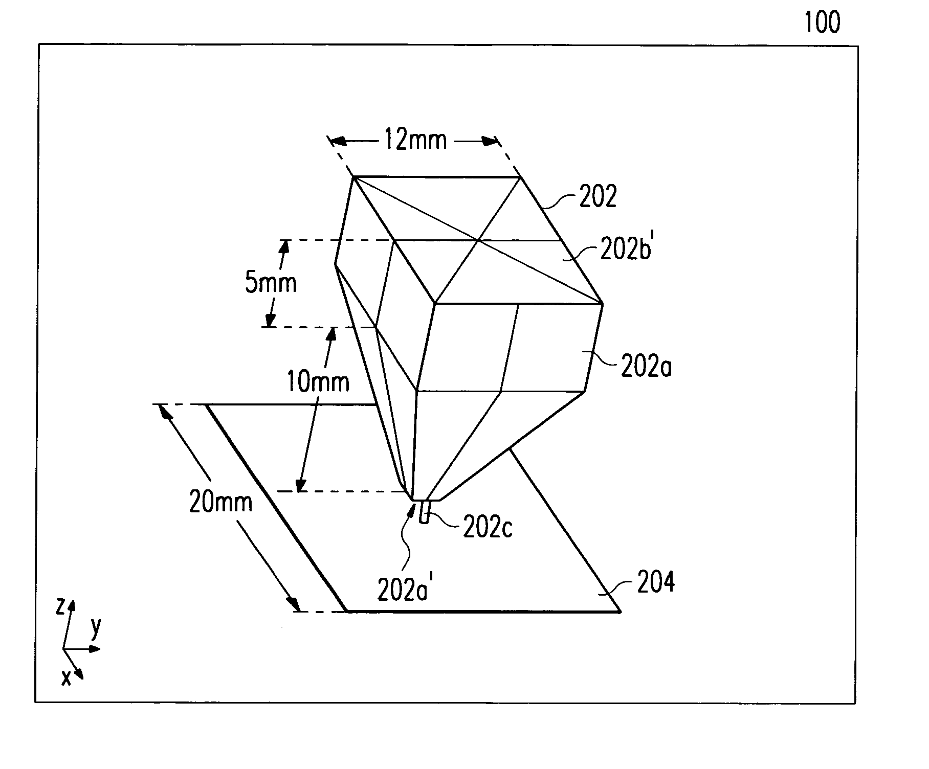
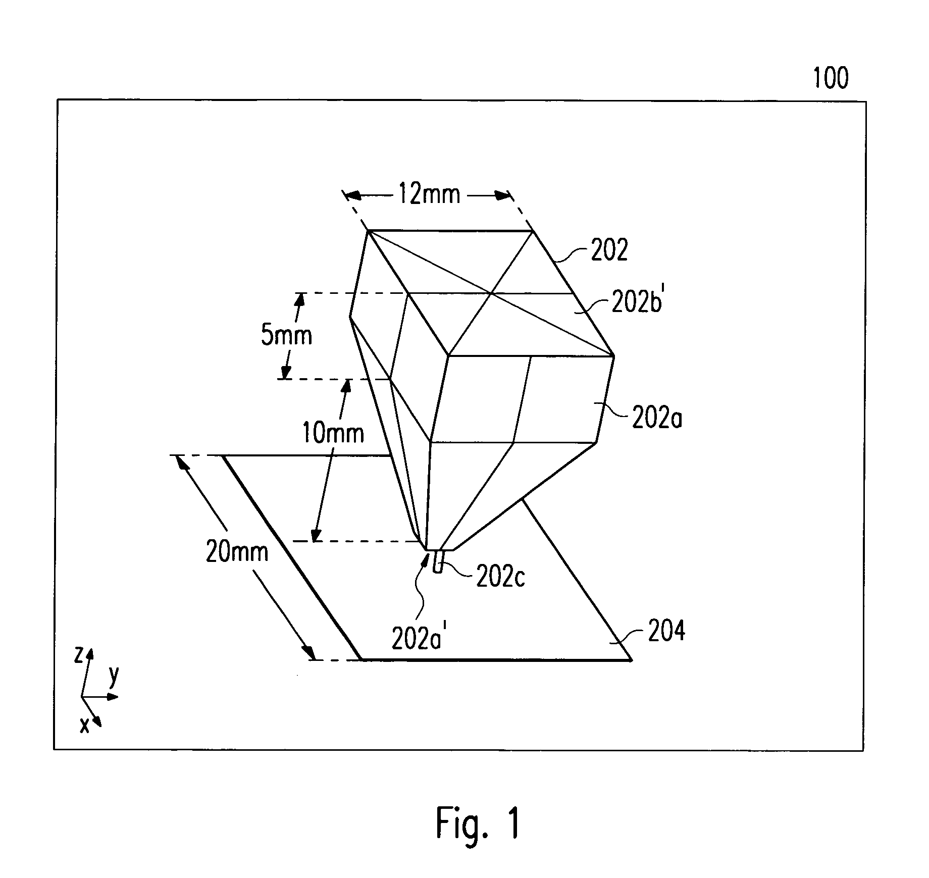
[0032] FIGS. 1 to 3l shall be explained in detail. The meaning of the symbols designated with reference numerals in FIGS. 1 to 3l can be taken from an annexed table.

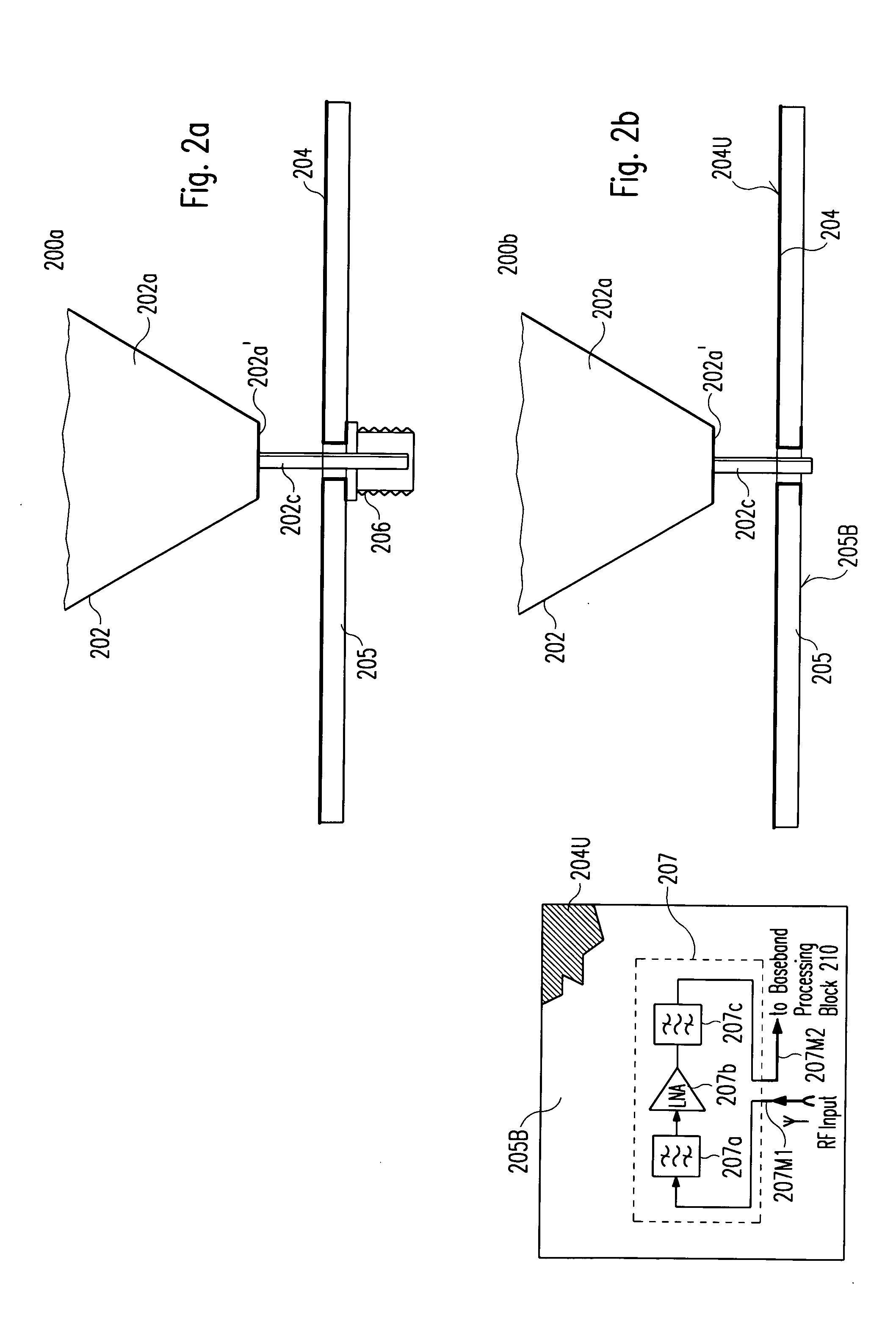
[0033]FIGS. 2a-c show the radiation element 202, which is made of copper, aluminum or any metallic components. The radiation element 202 can also be made of wood or plastic covered by a metallic print, its pedestal 202c, and the RF connector 206 of the ultra-wideband monopole antenna 100. Said pedestal 202c is attached to a dielectric substrate 205 onto which a metallic ground plane 204 is printed. The RF connector 206 is used for connecting the radiation element 202 with a baseband processing block 210 (in receive case) used for down-converting received microwave signals from the RF band to the baseband or with an antenna feeding circuitry 211 (in transmit case) used for electronically steering the symmetrical omni-directional rad...


PUM


Abstract

The present invention generally relates to the field of microwave antennas, and, more particularly, to a number of three-dimensional designs for the radiation element of an ultra-wideband monopole antenna with a symmetrical omni-directional radiation pattern operated in the frequency range between 3.1 GHz and 10.6 GHz. Said antenna is connected to the analog front-end circuitry of a wireless communication device used for transmitting and/or receiving microwave signals and meets the FCC requirements in terms of antenna gain, radiation pattern, polarization, frequency bandwidth, group delay, and size. It comprises a radiation element consisting of an air- and/or dielectric-filled cavity structure with a base plane and a radiator plane. A metallic ground plane having a relatively high surface impedance to electromagnetic waves within said frequency range, which is printed on a dielectric substrate, serves as a reflector. The monopole antenna further comprises an antenna feeding circuitry used for electronically steering the symmetrical omni-directional radiation pattern and a feeding line connecting the antenna feeding circuitry with the base plane of the radiation element. Thereby, parts of the analog front-end circuitry can optionally be placed within the air-filled part of the radiation element of the antenna. The proposed designs include a radiation element having the form of a truncated right circular cone, rotational-symmetric radiation elements with a convexly- or concavely-shaped 3D surface, respectively, a radiation element in the form of a truncated right regular pyramid with a square base plane, and radiation elements with a combined structure comprising a conical, pyramidal, convexly- or concavely-shaped first part and a closed cylindrical or cuboidal second part whose top plane is arranged on top of the congruent base plane of said first part. Further embodiments include radiation elements with the form of a radially notched cylinder or hemisphere as well as combined structures consisting of at least two convexly-shaped elements or two conical parts, respectively, stacked on top of each other.

Description

FIELD AND BACKGROUND OF THE INVENTION [0001] The present invention generally relates to the field of microwave antennas, and more particularly, to three-dimensional designs for the radiation element of an ultra-wide-band (UWB) monopole antenna with a symmetrical omni-directional radiation pattern for transmitting and / or receiving microwave signals. [0002] UWB generally covers a frequency range between 3.1 GHz and 10.6 GHz. A FCC definition is given e.g. in IEEE 802.15 the disclosure of which is hereby incorporated by reference. According to the IEEE 802.15 Working Group for Wireless Personal Area Networks (see e.g. http: / / www.ieee802.org / 15 / ) the 802.15 WPAN™ effort focuses on the development of Personal Area Networks or short distance wireless networks. These WPANs address wireless networking of portable and mobile computing devices such as PCs, Personal Digital Assistants (PDAs), peripherals, cell phones, pagers, and consumer electronics; allowing these devices to communicate and ...

Claims


Application Information

Patent Timeline
IPC IPC(8): H01Q13/08H01Q9/28H01Q9/30H01Q9/38H01Q9/40H01Q23/00
CPCH01Q9/28H01Q23/00H01Q9/40H01Q9/30
Inventor RATNI, MOHAMEDKRUPEZEVIC, DRAGAN
Owner SONY DEUT GMBH
Why Eureka
Try Eureka