3D visualization system

a 3d visualization and system technology, applied in the field of three-dimensional video, can solve problems such as the discovery of sfp methods

Active Publication Date: 2011-06-09
PHOTON
View PDF22 Cites 45 Cited by
  • Summary
  • Abstract
  • Description
  • Claims
  • Application Information

AI Technical Summary

Benefits of technology

[0012]The following summary presents a simplified summary in order to provide a basic understanding of some aspects of the systems and / or methods discussed herein. This summary is not an extensive overview of the systems and / or methods discussed herein. It is not intended to identify key / critical elements or to delineate the scope of such systems and / or methods. Its sole purpose is to present some concepts in a simplified form as a prelude to the more detailed description that is presented later.
[0013]In accordance with one aspect, the present invention provides a real-time 3D visualization system. The system includes means for conveying electromagnetic energy emanating from one or more 3D surfaces included by a scene and means for sensing spatial phase characteristics of the electromagnetic energy as the configuration of the 3D surfaces relative to the system changes. The system includes means for creating a 3D scene model utilizing the spatial phase characteristics sensed in a plurality of configurations and means for displaying the 3D scene model in real-time. The means for displaying includes means for synthesizing depth cues.

Problems solved by technology

The first Barbour patent, U.S. Pat. No. 5,557,261, discloses a video system for detecting ice on surfaces such as aircraft wings based on polarization of electromagnetic energy, but does not disclose a SfP method.

Method used


Image

  • 3D visualization system
  • 3D visualization system
  • 3D visualization system

Examples


first embodiment

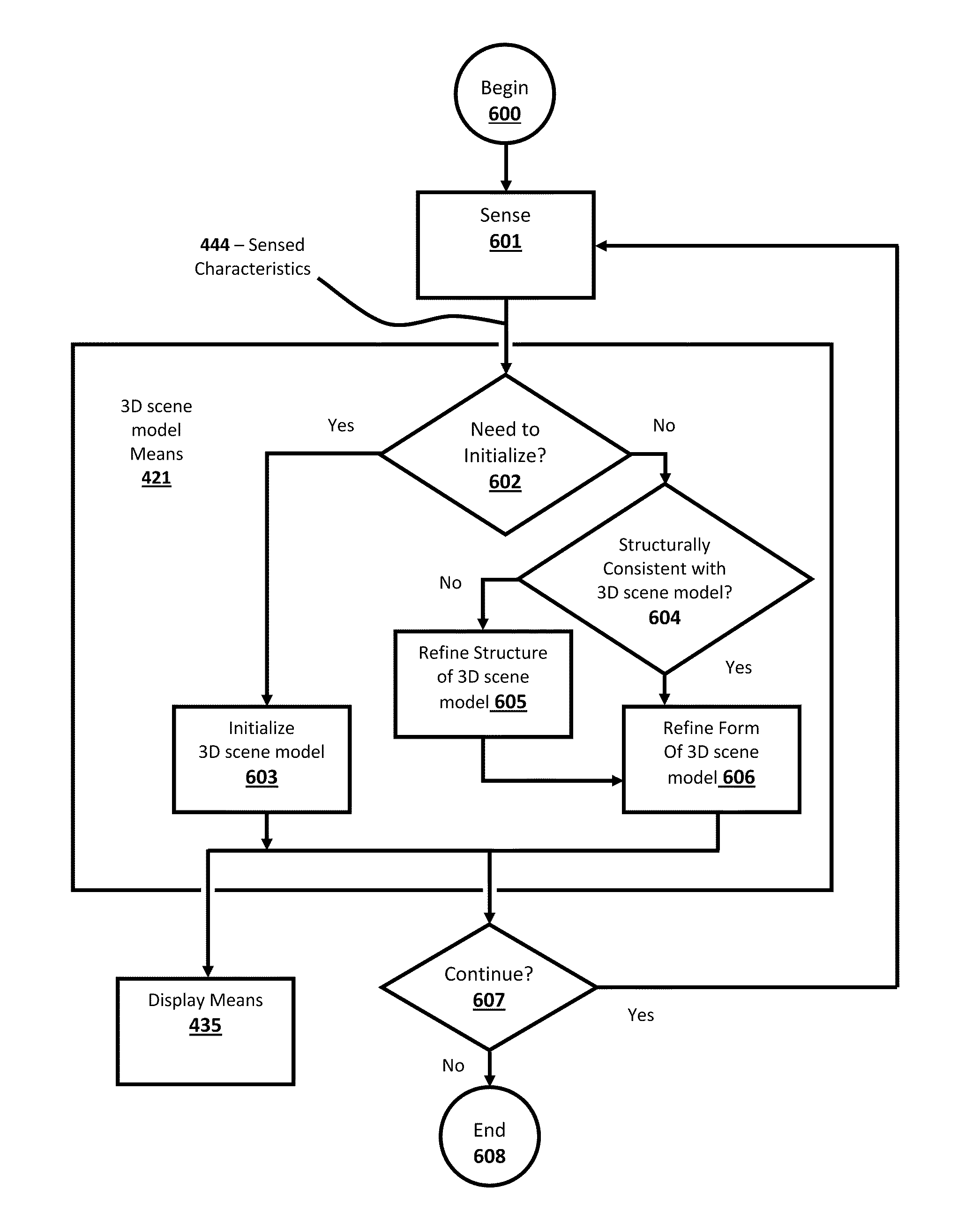
[0063]The first embodiment, aspects of which are schematically depicted in FIGS. 4A through 9, is a passive 3D thermal camera. This embodiment represents a useful device for military personnel and firemen, among others. It is described, in part, to emphasize the fact that New Apparatus do not need to benefit from visible light or conventional computer vision algorithms which rely on intensity contrast (freckles, spots, colors). Rather new algorithms based entirely on physical texture (crevices, bumps, form) form the basis of the algorithms used by the first embodiment. The primary benefit of a thermal camera is that images can be formed in the complete absence of visible light. Thus, thermal cameras enable people to “see” in the dark. This is because objects at or near room temperature strongly emit electromagnetic energy (like “light bulbs”) in the infrared (IR) spectral range. There are other benefits to thermal cameras which depend on wavelength. For example, thermal images at lo...


PUM


Abstract

In accordance with one aspect, the present invention provides a real-time 3D visualization system. The system includes means for conveying electromagnetic energy emanating from one or more 3D surfaces including a scene and means for sensing spatial phase characteristics of the electromagnetic energy as the configuration of the 3D surfaces relative to the system changes. The system includes means for creating a 3D scene model utilizing the spatial phase characteristics sensed in a plurality of configurations and means for displaying the 3D scene model in real-time. The means for displaying includes means for synthesizing depth cues.

Description

RELATED APPLICATIONS[0001]The present application claims benefit of priority of the following provisional patents, the disclosures of which are incorporated herein by reference:[0002]U.S. Patent Application No. 61 / 267,311, filed Dec. 7, 2009,[0003]U.S. Patent Application No. 61 / 300,207, filed Feb. 1, 2010,[0004]U.S. Patent Application No. 61 / 303,077, filed Feb. 10, 2010, and[0005]U.S. Patent Application No. 61 / 374,432, filed Aug. 17, 2010.FIELD OF THE INVENTION[0006]The present invention relates to the field of three-dimensional video, particularly high-fidelity three-dimensional video for applications including broadcasting, cinematography, gaming, home & business video and conferencing.BACKGROUND OF THE INVENTIONDiscussion of Prior Art[0007]A review of the literature reveals related approaches and art which are discussed below. Within the discussion it should be noted that SPI Cameras are 3D cameras that sense spatial phase characteristics; and SfP is an acronym for Shape from Pha...

Claims


Application Information

Patent Timeline
Patent Type & Authority Applications(United States)
IPC IPC(8): H04N13/04
CPCG06T15/00H04N13/0207H04N13/207
Inventor BARBOUR, BLAIR ALLENACKERSON, DAVID SCOTT
Owner PHOTON
Why Eureka
Try Eureka