

Blade with 3D platform comprising an inter-blade bulb
- Summary
- Abstract
- Description
- Claims
- Application Information
AI Technical Summary
Benefits of technology
Problems solved by technology
Method used
Image

Examples
Embodiment Construction
[0050]It should be noted that for the sake of simplicity, if an element appears on various figures, identically or in a slightly different form, the same number is assigned thereto in the various figures, and the element is described only the first time it is mentioned.
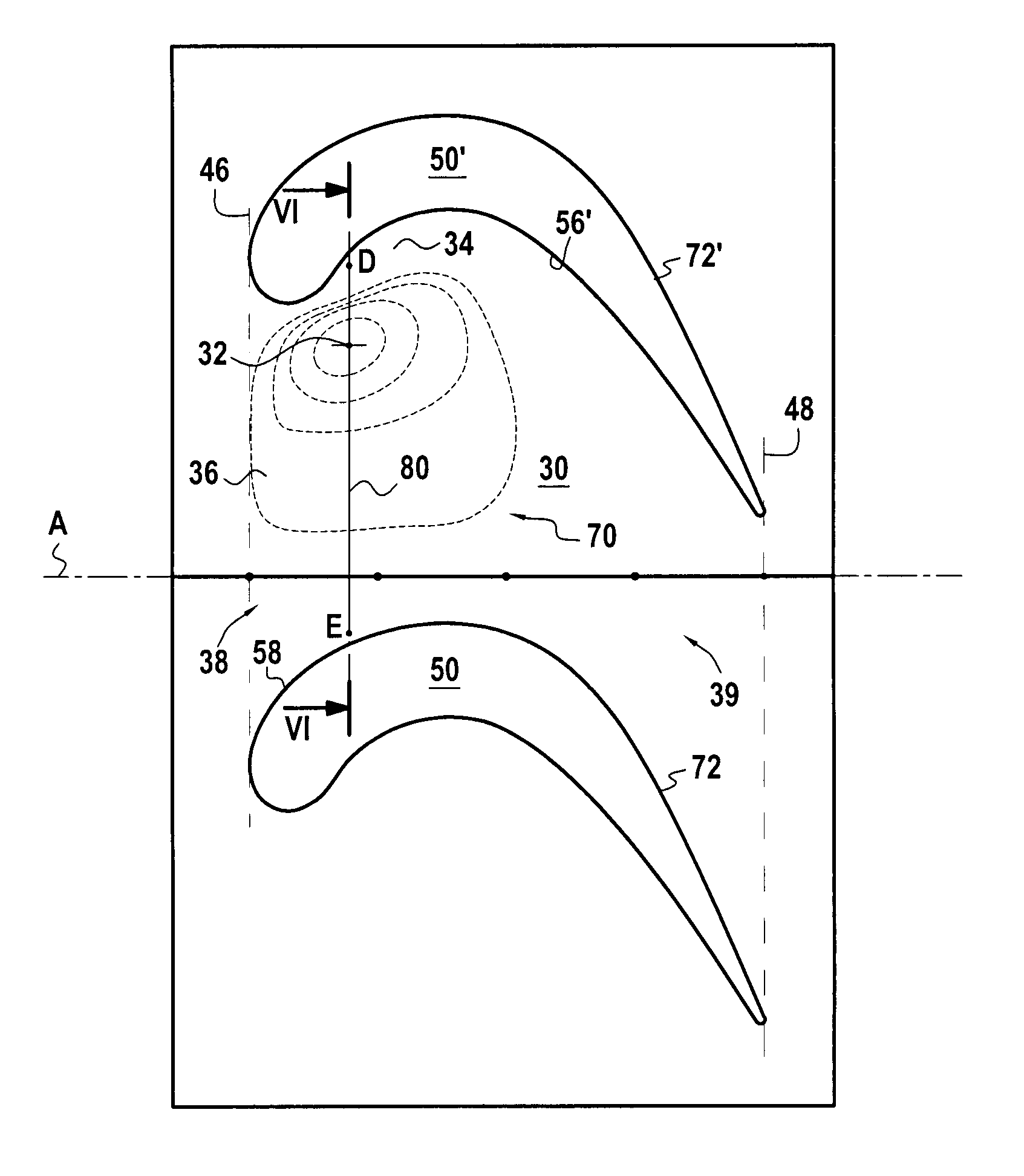
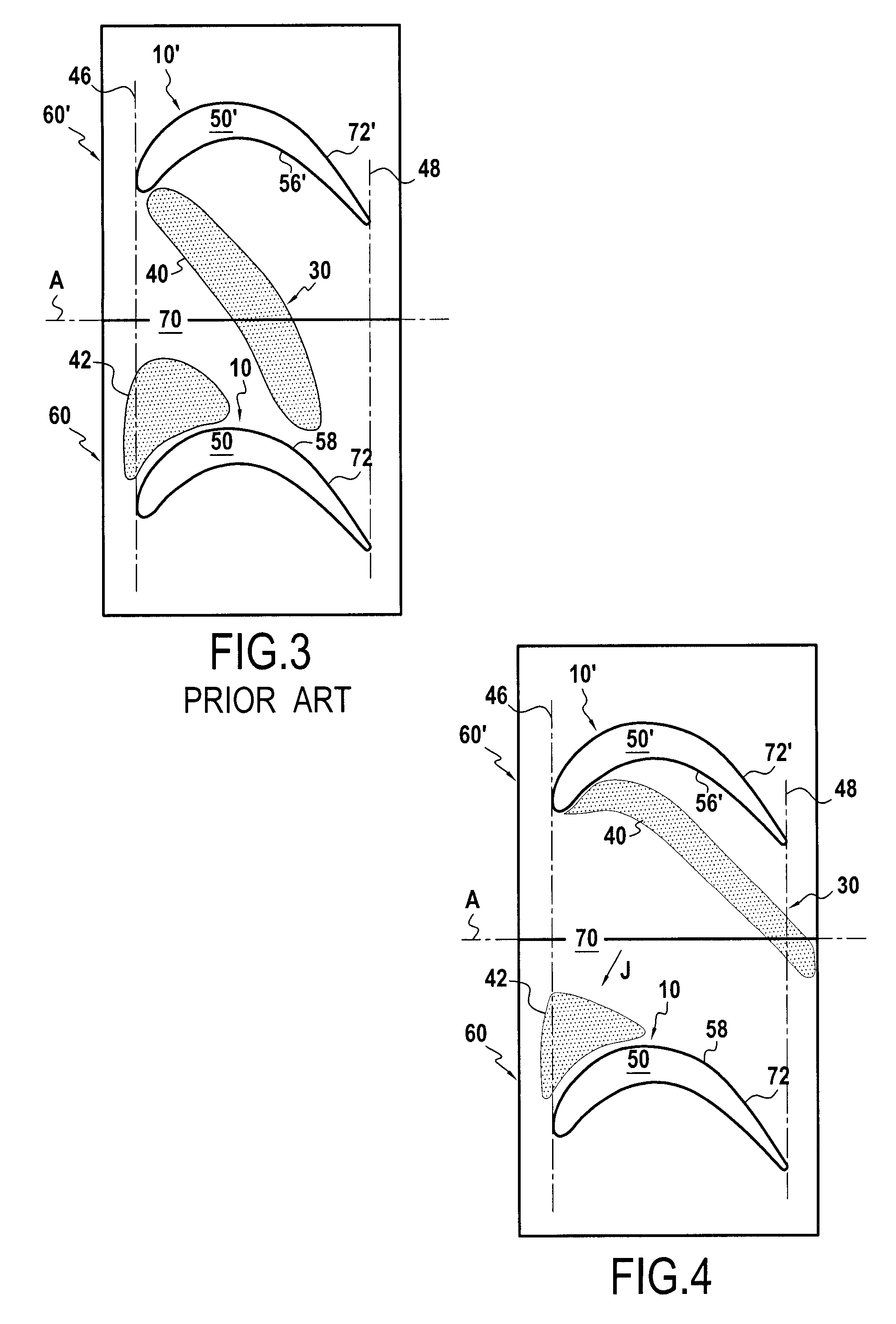
[0051]With reference to FIG. 4, we will now describe the effect produced on the pressure field in the inter-airfoil channel by a blade according to the invention.
[0052]The present invention defines a platform surface shape allowing to minimize stray turbulent phenomena close to the inter-airfoil surface, and thereby to increase the efficiency of the blade and thus the impeller. Comparing FIGS. 3 and 4 shows the relative effect of the invention on the pressure field in the inter-airfoil channel 30 allowing to obtain the specific shape of an inventive blade.
[0053]While in FIG. 3, areas 40, 42, respectively of high and low pressure, are relatively close to each other, in FIG. 4, it can be seen that they are further apart...
PUM
 Abstract
Description
Claims
Application Information