Eureka AIR delivers breakthrough ideas for toughest innovation challenges, trusted by R&D personnel around the world.

Wafer Level Integrated Circuit Contactor and Method of Construction

Active Publication Date: 2013-12-26
JOHNSTECH INT
View PDF2 Cites 18 Cited by
  • Summary
  • Abstract
  • Description
  • Claims
  • Application Information

AI Technical Summary

Benefits of technology

The patent describes a method for accurately locating and engaging the corners and sidewalls of a retainer plate and a pin guide plate. This is important for ensuring proper alignment and stability during use. Additionally, the method can involve cutting away or forming the corners to ensure that they are not mismatched and proper engagement is achieved. The technical effect of this invention is to provide a reliable and effective method for engaging parts in a simple and precise way, which can improve the overall performance and reliability of the overall system.

Problems solved by technology

The technology used for testing IC leaded packages therefore is not particularly analogous to wafer level testing and we have found principles from IC packed lead testing will not work without substantial modification and inventive input.

Method used


Image

  • Wafer Level Integrated Circuit Contactor and Method of Construction
  • Wafer Level Integrated Circuit Contactor and Method of Construction
  • Wafer Level Integrated Circuit Contactor and Method of Construction

Examples


Embodiment Construction

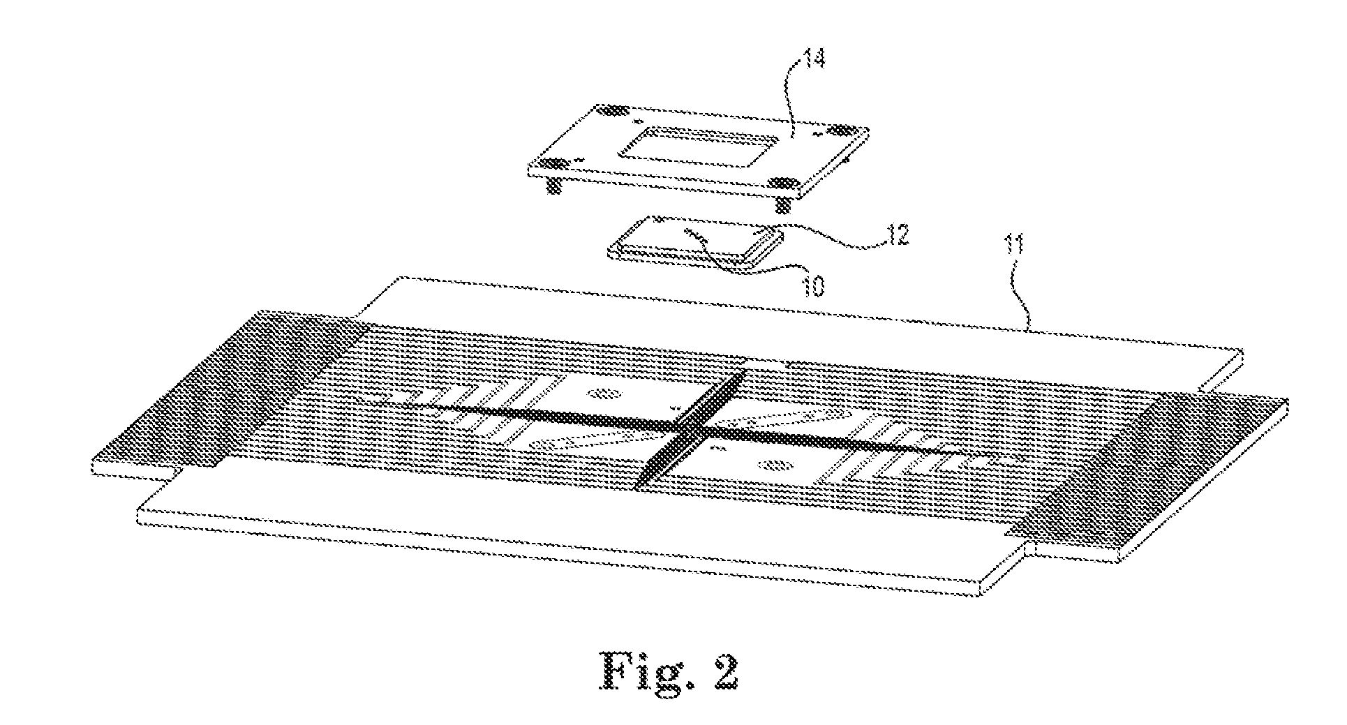
[0075]A typical IC wafer contains between 1k-22k dies typically organized in a regular matrix separated by horizontal and vertical scribe lines, for later cutting into individual dies or chips to be mounted in an IC enclosure with leads or contacts. This disclosure is primarily directed to testing of an individual dies or groups of dies in an array such as a pattern of generally geographically adjacent dies, or multiple arrays simultaneously, before they are cut along the scribe lines, whereafter, each die is inserted into an IC package with leads or contacts.

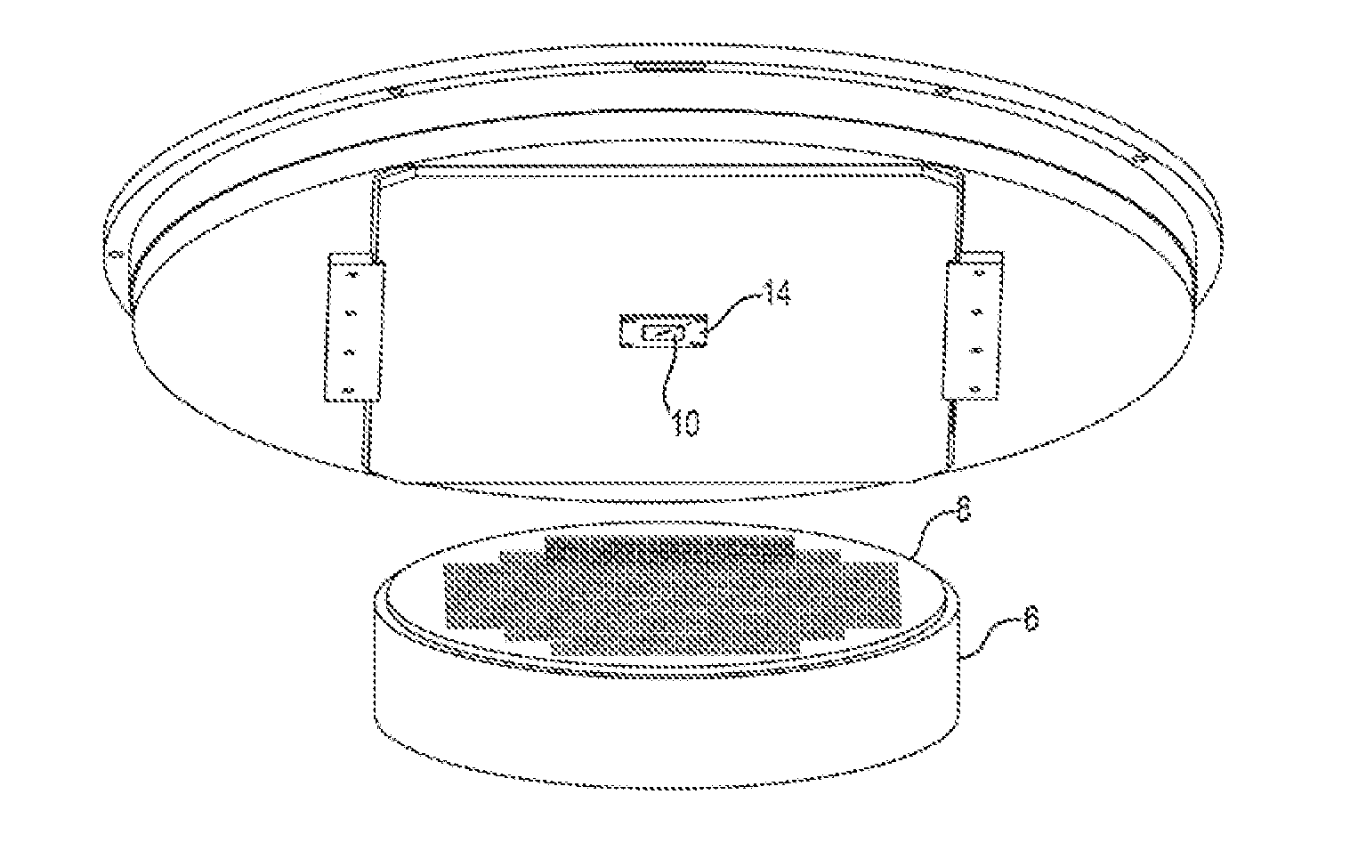
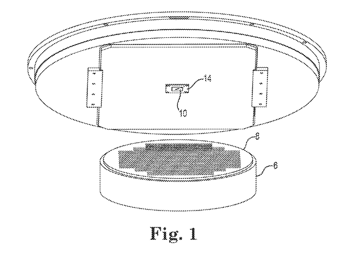
[0076]In the preferred embodiment, as shown in FIGS. 1 and 2, a probe array of contacts 10 is held, preferably close press fit registration to prevent movement, into a pin guide plate / pin guide 12 which itself is affixed onto probe card plate 14 by means of a retainer. Said retainer may include a picture frame opening which has a stepped ledge to accommodate a like ledge on the pin guide plate 12. It is preferable to restrict f...


PUM

PropertyMeasurementUnit
Diameteraaaaaaaaaa
Shapeaaaaaaaaaa
Radiusaaaaaaaaaa

Abstract

A testing device for wafer level testing of IC circuits is disclosed. An upper and lower pin (22, 62) are configured to slide relatively to each other and are held in electrically biased contact by an elastomer (80). The elastomer is precompressed from its natural rest state between a top (22) plate and a bottom (70). Pre compression improves the resilient response of the pins. The pin crows (40) are maintained relatively coplanar by the engagement of at least one flang (44a-b) against an up-stop surface 90 of plate 20, thereby insuring coplanarity of the crowns. The pin guide (12) is maintained in alignment with the retainer 14 by establishing a registration corner (506) and driving the guide into the corner by elastomers in at least one diagonally opposite corner.

Description

CROSS-REFERENCE TO RELATED APPLICATIONS[0001]This applications claims priority of and incorporates by reference in its entirety, the following applications: US-2010 / 0231251-A1 (U.S. Ser. No. 12 / 721,039) filed 10 Mar. 2010; U.S. Ser. No. 13 / 343,328 filed 4 Jan. 2012 as a CIP of Ser. No. 13 / 226,606 which claims priority to provisional 61 / 380,494 filed 7 Sep. 2010 and 61 / 383,411 filed 16 Sep. 2010 and US-2012 / 0092034-A1 (U.S. Ser. No. 13 / 276,893) filed 19 Oct. 2011 which itself is a CIP of Ser. No. 12 / 764,603 filed 21 Apr. 2010 which claims 61 / 171141 filed 21 Apr. 2009, 61 / 257,236 filed 2 Nov. 2009 and 61 / 307,501 filed 24 Feb. 2010.BACKGROUND[0002]1. Field of the Disclosure[0003]The present invention concerns integrated circuit fabrication and testing. More particularly, the present invention concerns a methodology and structure for testing multiple integrated circuit dies residing on a semiconductor wafer substrate.[0004]2. Description of the Related Art[0005]Conventional integrated c...

Claims


Application Information

Patent Timeline
IPC IPC(8): G01R1/073G01R3/00
CPCG01R1/07307G01R3/00G01R1/06733Y10T29/49204G01R1/07314G01R31/2601
Inventor EDWARDS, JATHANMARKS, CHARLESHALVORSON, BRIAN
Owner JOHNSTECH INT
Why Eureka
Eureka Blog
Learn More