Lower Mill Spaced Cutting Ring Structure

a cutting ring and lower mill technology, applied in the field of window milling, can solve the problems of rotary torque increase, mill lock-up, and lower mill blades, and achieve the effects of increasing the contact stress of inserts, reducing rotary torque, and reducing rotary torqu

Active Publication Date: 2015-06-04
BAKER HUGHES INC
View PDF3 Cites 6 Cited by
  • Summary
  • Abstract
  • Description
  • Claims
  • Application Information

AI Technical Summary

Benefits of technology

[0020]The cutting structure on the lower mill is arrayed in rows that are preferably parallel. The cutting structure in each row is made sharper and more durable than prior designs with the objective of cutting the window higher than where the window mill started the window. The use of the rows increases the contact stress of the inserts on the casing inside wall because at any given time fewer and sharper inserts are cutting the casing wall to lengthen the window. As a row wears down the next row takes over to continue the cutting where the previous row was active and to further penetrate the casing wall. The cutout angle can also increase as this occurs. As a result a decreased insert density results in more effective casing wall cutting to extend the window to allow larger tools to exit into the window off the whipstock.

Problems solved by technology

If the lower diameter is large and the blades are long, the front and back of the blades can contact the opposite sides of the casing and cause the mill to lock up.
When the lower spans the angle change at the top of the whipstock, it interferes with the casing at the top of the window, so the rotary torque increases at this point.
If the BHA bending is excessive; the stress below the lower mill blades will be high enough to crack the body from fatigue.
It is difficult for the window mill to first mill through the casing, and excessive bending further increases the force required.
The lower needs some load against the casing for cutting, but excessive load wears the cutting structure quickly and can make the mill too smooth to cut effectively.
If this restoring side force into the whipstock is too large, the bending stress on the lower will be excessive and it will fail in a short period of time.
A high force will also increase window mill wear and the depth cut into the whipstock, which lowers the top of the window.
The objection to this design is a long length of cutting structure bearing on the casing slows the rate the mill cuts into the casing, which reduces the angle of the cut and lowers the top of the window (FIG. 1).
The long angle of engagement tends to wear a long taper on the cutting structure that further increases contact area.
The objection to this design is the after the initial cutters breakdown, there is no cutting structure left to continue cutting.

Method used


Image

  • Lower Mill Spaced Cutting Ring Structure
  • Lower Mill Spaced Cutting Ring Structure
  • Lower Mill Spaced Cutting Ring Structure

Examples


Embodiment Construction

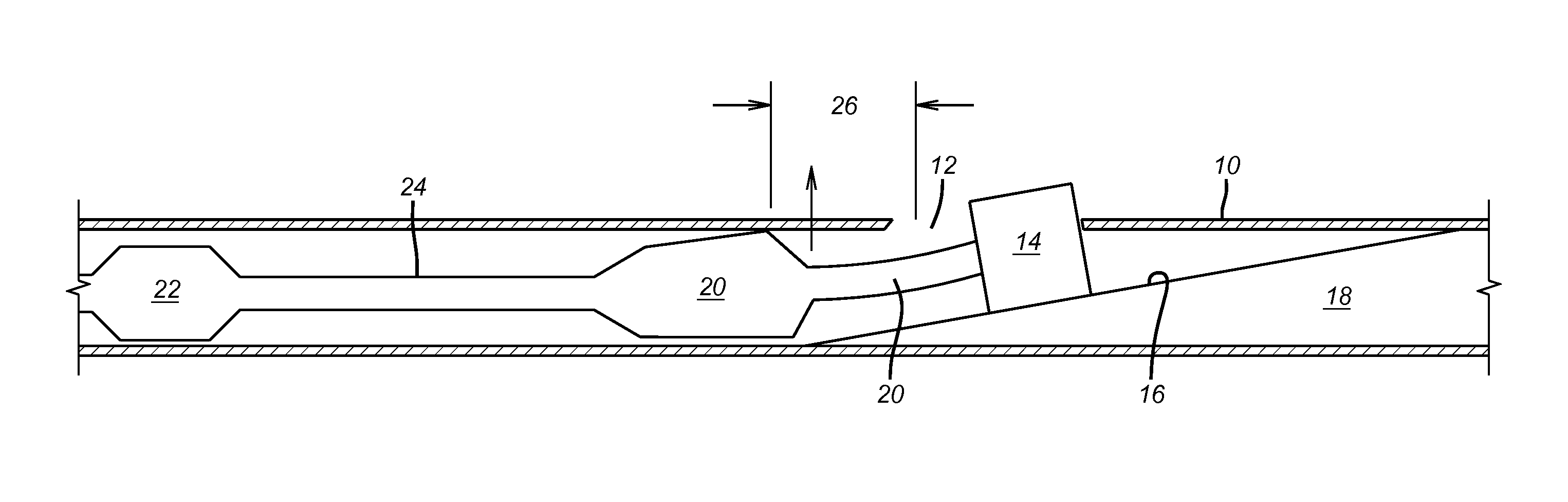
[0030]FIG. 6 illustrates a casing 10 where a window 12 is started with a window mill 14 running on a ramp 16 of a whipstock 18. A connector 20 connects the whipstock 18 to the lower mill 20. The upper mill 22 is connected to the lower mill 20 by connector 24. The present invention is focused on milling away more casing wall in zone 26 to extend the window 12 length so that larger assemblies can make the turn into the lateral beyond the window 12. At the same time the objective is also to enhance the milling time as well as to get a longer running time for the lower mill 20.

[0031]Comparing FIGS. 4 and 5 it can be seen that the prior design of FIG. 4 added inserts 30 to the blade faces 32 in a very densely packed manner with the idea of putting as much cutting structure at these locations as possible. What this accomplished however was very low contact stress and far less cutting of the wall of the tubular. Instead the inserts simply wore down a part of the inside surface of the tubul...


PUM


Abstract

The cutting structure on the lower mill is arrayed in rows that are preferably parallel. The cutting structure in each row is made sharper and more durable than prior designs with the objective of cutting the window higher than where the window mill started the window. The use of the rows increases the contact stress of the inserts on the casing inside wall because at any given time fewer and sharper inserts are cutting the casing wall to lengthen the window. As a row wears down the next row takes over to continue the cutting where the previous row was active and to further penetrate the casing wall. The cutout angle can also increase as this occurs. As a result a decreased insert density results in more effective casing wall cutting to extend the window to allow larger tools to exit into the window off the whipstock.

Description

FIELD OF THE INVENTION[0001]The field of the invention is window milling and more particularly milling with a window mill and at least a lower mill above for extending and widening the window cut by the window mill using a cutter layout on a lower mill that promotes a higher location of the top of window.BACKGROUND OF THE INVENTION[0002]A whipstock is a long, hardened steel wedge that forces a window mill to cut out through the side of casing to create a window. The smaller the angle change at the top of the whipstock, the larger the drilling assembly that can span across the angle change at top of whipstock, and so pass through the window. Smaller angles require longer windows and more metal to be cut. Whipstock angle is typically referred to as a measure of dogleg severity, but it is actually degrees of angle change per 100 ft. Since the angle changes abruptly at the top of whipstock, this measure is technically infinite. Instead it is assumed that the angle of the pipe changes ov...

Claims


Application Information

Patent Timeline
Patent Type & Authority Applications(United States)
IPC IPC(8): E21B29/00
CPCE21B29/005E21B7/061E21B29/06E21B10/46
Inventor STOWE, CALVIN J.GHEGADMAL, TEJAS J.PONDER, ANDREW D.
Owner BAKER HUGHES INC
Why Eureka
Try Eureka