Vehicle braking system

a technology for braking systems and vehicles, applied in braking systems, analogue processes for specific applications, instruments, etc., can solve problems such as difficulty in accurately controlling brake pressure to be equal to a target brake pressure, and achieve the effect of finely controlling brake pressure and stabilizing vehicle behavior

Active Publication Date: 2015-06-11
HONDA MOTOR CO LTD
View PDF36 Cites 1 Cited by
  • Summary
  • Abstract
  • Description
  • Claims
  • Application Information

AI Technical Summary

Benefits of technology

[0013]According to the present invention with the above feature, since the hydraulic-pressure generation control unit brings to zero the predetermined hydraulic pressure generated by the hydraulic-pressure generation device, the control of the braking force for stabilizing the vehicle behavior can be finely performed by the second vehicle-behavior stabilization control unit.
[0014]According to the present invention, it is possible to provide a vehicle braking system which can finely control the braking force for stabilizing the vehicle behavior.

Problems solved by technology

Therefore, when the braking force generated in the slave cylinder is added to the small braking force as above, it is difficult to accurately control the brake pressure to be equal to a target brake pressure.

Method used


Image

  • Vehicle braking system
  • Vehicle braking system
  • Vehicle braking system

Examples


Embodiment Construction

[0022]Hereinbelow, an embodiment of the present invention is explained below.

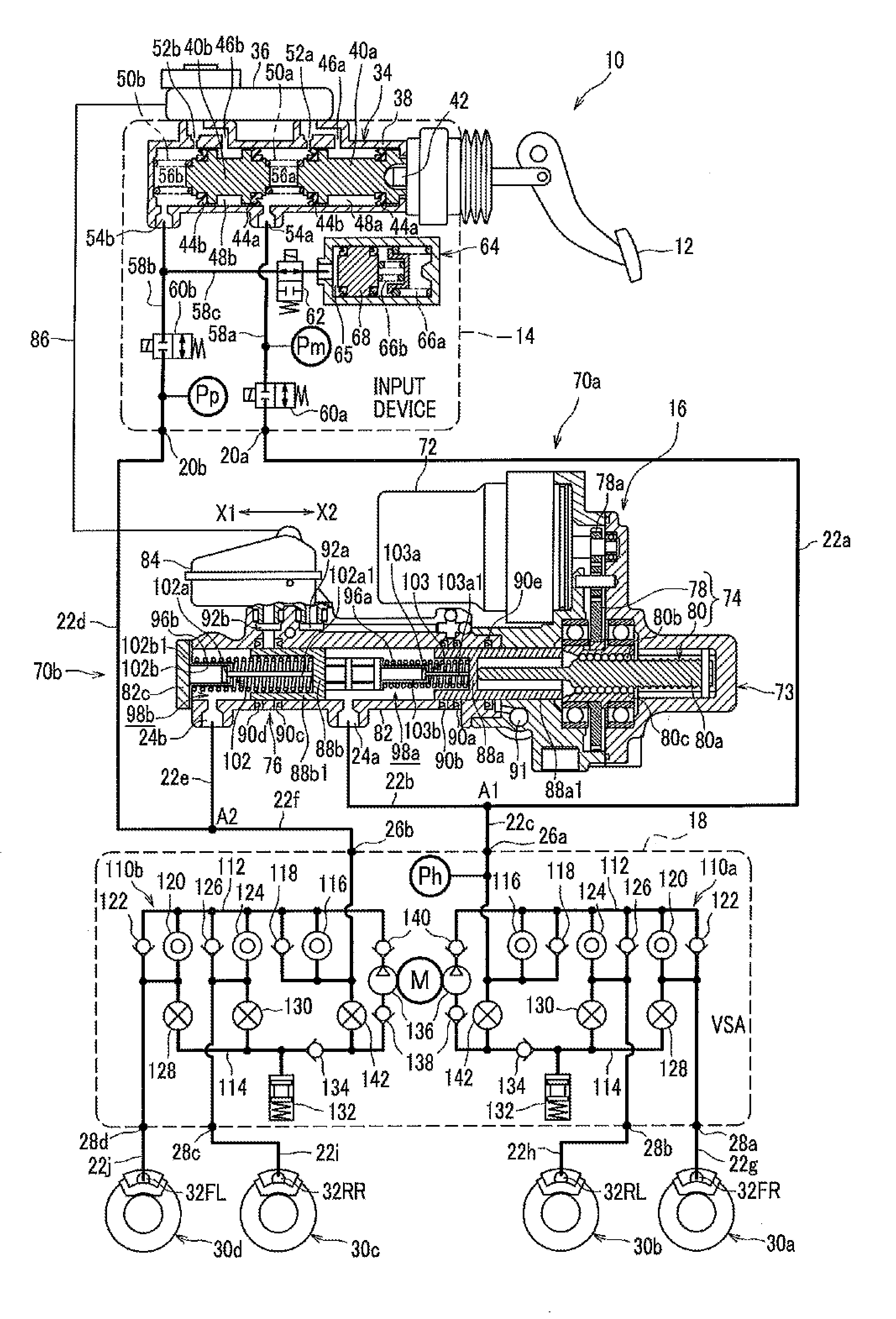
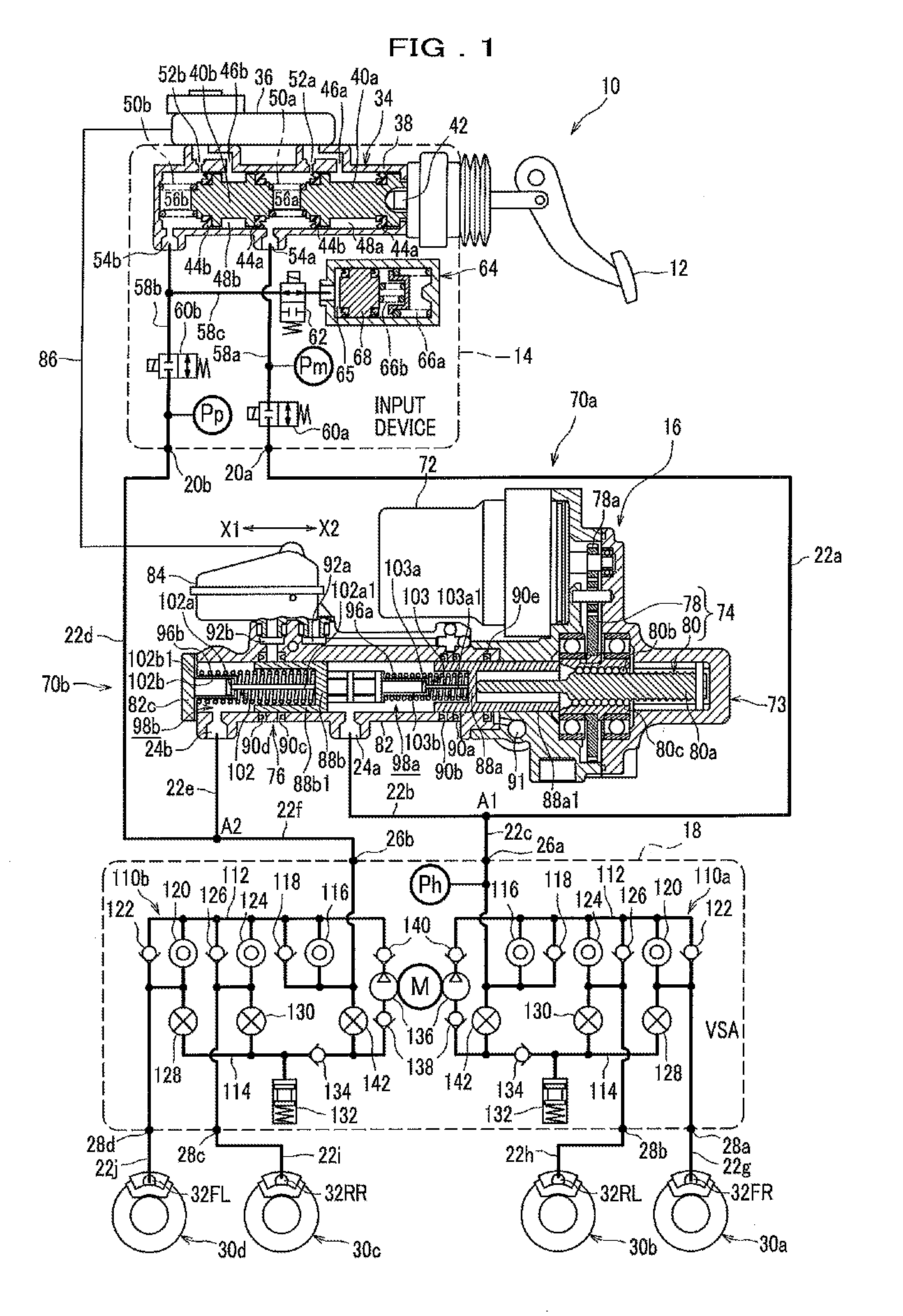
[0023]FIG. 1 is a schematic diagram illustrating the configuration of a vehicle braking system 10. The vehicle braking system 10 is mounted on a vehicle (specifically, the vehicle 300, which is explained later). First, the hydraulic paths are explained. A connection port 20a of an input apparatus 14 is connected to a connection point A1 (which is indicated in FIG. 1 and regarded as a reference point) through a first piping tube 22a, an outlet port 24a of a slave cylinder 16 (as a hydraulic-pressure generation device) is connected to the connection point A1 through a second piping tube 22b, and an inlet port 26a of a vehicle-behavior stabilization device 18 is connected to the connection point A1 through a third piping tube 22c.

[0024]In addition, another connection port 20b of the input apparatus 14 is connected to another connection point A2 (which is regarded as another reference point) through a fourth p...


PUM


Abstract

In a vehicle braking system for stabilizing vehicle behavior: a motor control unit determines whether or not the motor control unit receives a drive forbid signal from a yaw-moment control unit, when the motor control unit receives a drive instruction signal from a vehicle-behavior stabilization control unit. The motor control unit receives the drive forbid signal when the yaw-moment control unit performs yaw-moment control. The motor control unit forbids prepressurization using a slave cylinder, when the motor control unit receives the drive forbid signal.

Description

CROSS REFERENCE TO RELATED APPLICATION[0001]This application claims the foreign priority benefit under Title 35, United States Code, §119(a)-(d) of Japanese Patent Application No. 2013-255688, filed on Dec. 11, 2013 in the Japan Patent Office, the disclosure of which is herein incorporated by reference in its entirety.BACKGROUND OF THE INVENTION[0002]1. Field of the Invention[0003]The present invention relates to a vehicle braking system.[0004]2. Description of the Related Art[0005]Japanese Patent Laid-open No. 2009-227023 (which is hereinafter referred to as JP2009-227023A) discloses the following technique. According to the disclosed technique, at the start of operation of a yaw-moment control device, a slave cylinder is temporarily operated, a brake pressure generated in the slave cylinder is added to a brake pressure generated by the yaw-moment control device, and the sum of the brake pressures is outputted to wheel cylinders. The object of the above technique is to supplement d...

Claims


Application Information

Patent Timeline
Patent Type & Authority Applications(United States)
IPC IPC(8): B60T8/1755
CPCB60T8/17551B60T8/17554B60T8/17552B60T8/1755B60T2201/122
Inventor OHMURA, KAZUTAKAKOJIMA, TAKESHIFUTAMURA, TOMOYUKI
Owner HONDA MOTOR CO LTD
Why Eureka
Try Eureka