
Solvent extraction settler arrangement

a settler arrangement and solvent extraction technology, applied in solvent extraction, solvent extraction, liquid solution solvent extraction, etc., to achieve uniform mass flow distribution, reduce the generation of small droplets, and improve the effect of solvent extraction

Active Publication Date: 2015-06-11
METSO OUTOTEC (FINLAND) OY
View PDF7 Cites 9 Cited by
  • Summary
  • Abstract
  • Description
  • Claims
  • Application Information

AI Technical Summary

Benefits of technology

The invention provides a settler arrangement for separating liquids and gases in a tank. The multiple point feed of the dispersion ensures a uniform mass flow distribution, which eliminates the need for a single uptake channel and distribution fence. The conical shape of the feed launder minimizes the generation of small droplets and ensures a constant flow rate. The air-tight construction decreases evaporation of the reagent, lowering make-up costs. The feed launder made of a fibre-reinforced plastic composite or steel has the required strength and can be manufactured at lower costs than other methods. A level control valve connected to each feed pipe inside the feed launder can adjust the height position to control the flow of the dispersion. The settler consists of a tank with a single uniform flow space and all feed pipes open to it, ensuring accurate and efficient separation.

Problems solved by technology

The problem is that the single feed point feeding dispersion requires a distribution fence to be arranged near the feed end of the settler to distribute the flow of the dispersion to the whole width of the settler.

Method used


Image

  • Solvent extraction settler arrangement
  • Solvent extraction settler arrangement
  • Solvent extraction settler arrangement

Examples


Embodiment Construction

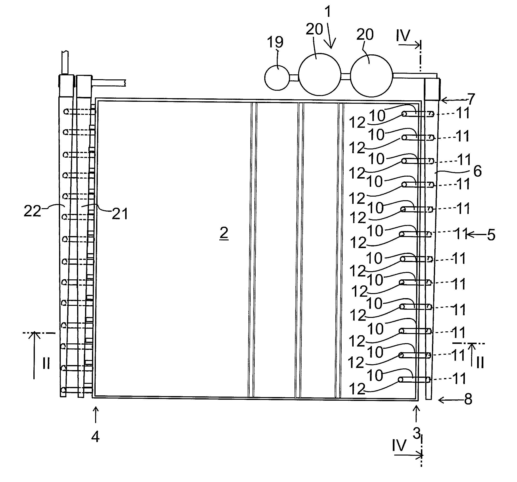
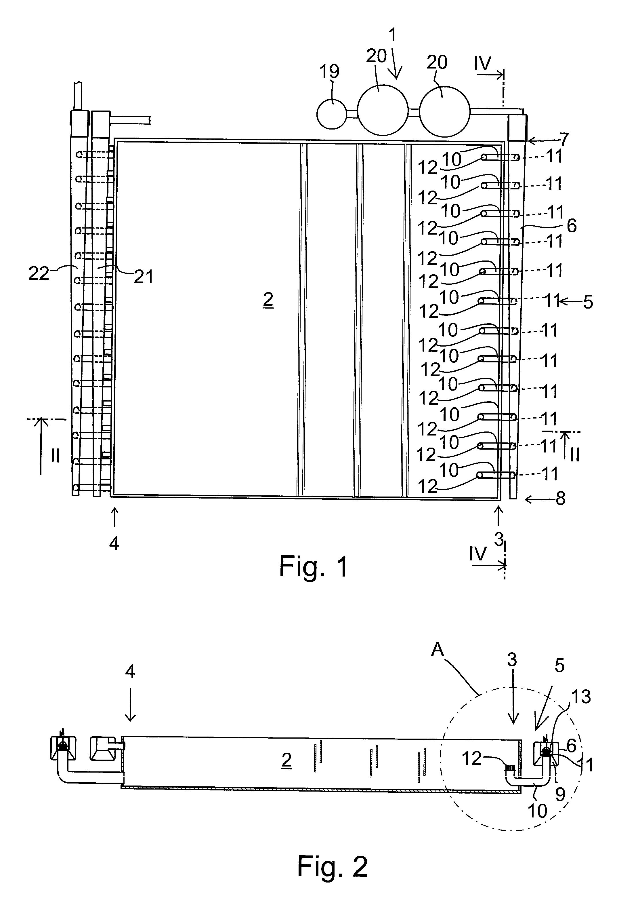
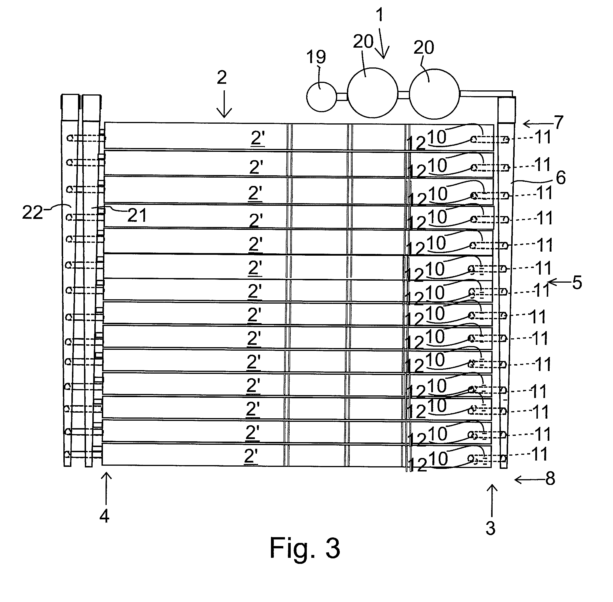
[0022]FIGS. 1 and 3 show solvent extraction settler arrangements which are adapted for hydrometallurgical liquid-liquid extraction processes.

[0023]The settler arrangement comprises a mixing unit 1 for preparing a dispersion from mutually immiscible solutions. The mixing unit 1 includes, in this case, a pumping unit 19 and two mixers 20. A settler 2 is arranged to separate solution phases from a dispersion which is fed from the feed end 3 while the dispersion flows towards the discharge end 4. A feeding device 5 is arranged at the feed end 3 for feeding the dispersion prepared by the mixing unit 1 to the settler 2. Discharge launders 21 and 22 are arranged at the discharge end 4 to receive and discharge the separated solutions.

[0024]The feeding device 5 comprises an elongated feed launder 6. From the mixing unit 1 the dispersion is conducted to a first end 7 of the feed launder 6. The feed launder 6 extends alongside the feed end 3 of the settler 2. The feed launder 5 has a form of a...


PUM

PropertyMeasurementUnit
lengthaaaaaaaaaa
heightaaaaaaaaaa
widthaaaaaaaaaa

Abstract

A solvent extraction settler arrangement comprising a mixing unit for preparing a dispersion from mutually immiscible solutions and a settler having a feed end and a discharge end. The settler is arranged to separate solution phases from a dispersion fed from the feed end while the dispersion flows towards the discharge end. The arrangement further comprises a feeding device located at the feed end for feeding the dispersion prepared by the mixing unit to the settler. The feeding device comprises an elongated feed launder having a first end for receiving the dispersion from the mixing unit, and a second end. The feed launder extends alongside the feed end of the settler. The feed launder has a form of a conical tube with a cross-section converging towards the second end and an inclined bottom ascending towards the second end. A plurality of feed pipes are arranged along the length of the feed launder at a distance from each other, each feed pipe having a third end opening to the inner space of the feed launder at the bottom to receive the dispersion from the feed launder and a fourth end opening to the settler to conduct the dispersion to the settler.

Description

FIELD OF THE INVENTION[0001]The present invention relates to a solvent extraction settler arrangement adapted for hydrometallurgical liquid-liquid extraction processes.BACKGROUND OF THE INVENTION[0002]As disclosed in e.g. publications WO 97 / 40899, WO 97 / 40900 and WO 97 / 41938 a solvent extraction settler arrangement is known which is adapted for hydrometallurgical liquid-liquid extraction processes and which typically comprises a mixing unit for preparing a dispersion from mutually immiscible solutions. A settler is arranged to separate solution phases from a dispersion fed from the feed end while the dispersion flows towards the discharge end of the settler. A feeding device is located at the feed end for feeding the dispersion prepared by the mixing unit to the settler.[0003]In the known technology the dispersion is fed into the settler at a single feed point located at the center of the feed end or in the vicinity thereof via an uptake channel. The problem is that the single feed ...

Claims


Application Information

Patent Timeline
Patent Type & Authority Applications(United States)
IPC IPC(8): C22B3/02B01D11/04C22B3/20
CPCC22B3/02B01D11/0484B01D11/0446C22B3/20B01D11/04B01D17/0214Y02P10/20
Inventor VAARNO, JUSSISAARIO, RAMIFREDRIKSSON, HENRI
Owner METSO OUTOTEC (FINLAND) OY
Learn More