System and method for sampling of fluid

a fluid sampling and fluid technology, applied in the field of fluid sampling systems and methods, can solve the problems of damage to nox sensors present in the exhaust outlet, inaccurate readings provided by nox sensors,

Inactive Publication Date: 2015-06-11
CATERPILLAR INC
View PDF2 Cites 11 Cited by
  • Summary
  • Abstract
  • Description
  • Claims
  • Application Information

AI Technical Summary

Problems solved by technology

However, in some situations, the NOx sensor may contact with a relatively small portion of the exhaust gas flow due to its position within an exhaust conduit of the exhaust system.
In such situations, the readings provided by the NOx sensor may still be inaccurate since the exhaust gas flow may contact a relatively small surface area of the NOx sensor.
Further, the NOx sensor present within the exhaust outlet may be subject to damage due to entry of water or debris into the exhaust outlet.

Method used


Image

  • System and method for sampling of fluid
  • System and method for sampling of fluid
  • System and method for sampling of fluid

Examples


Embodiment Construction

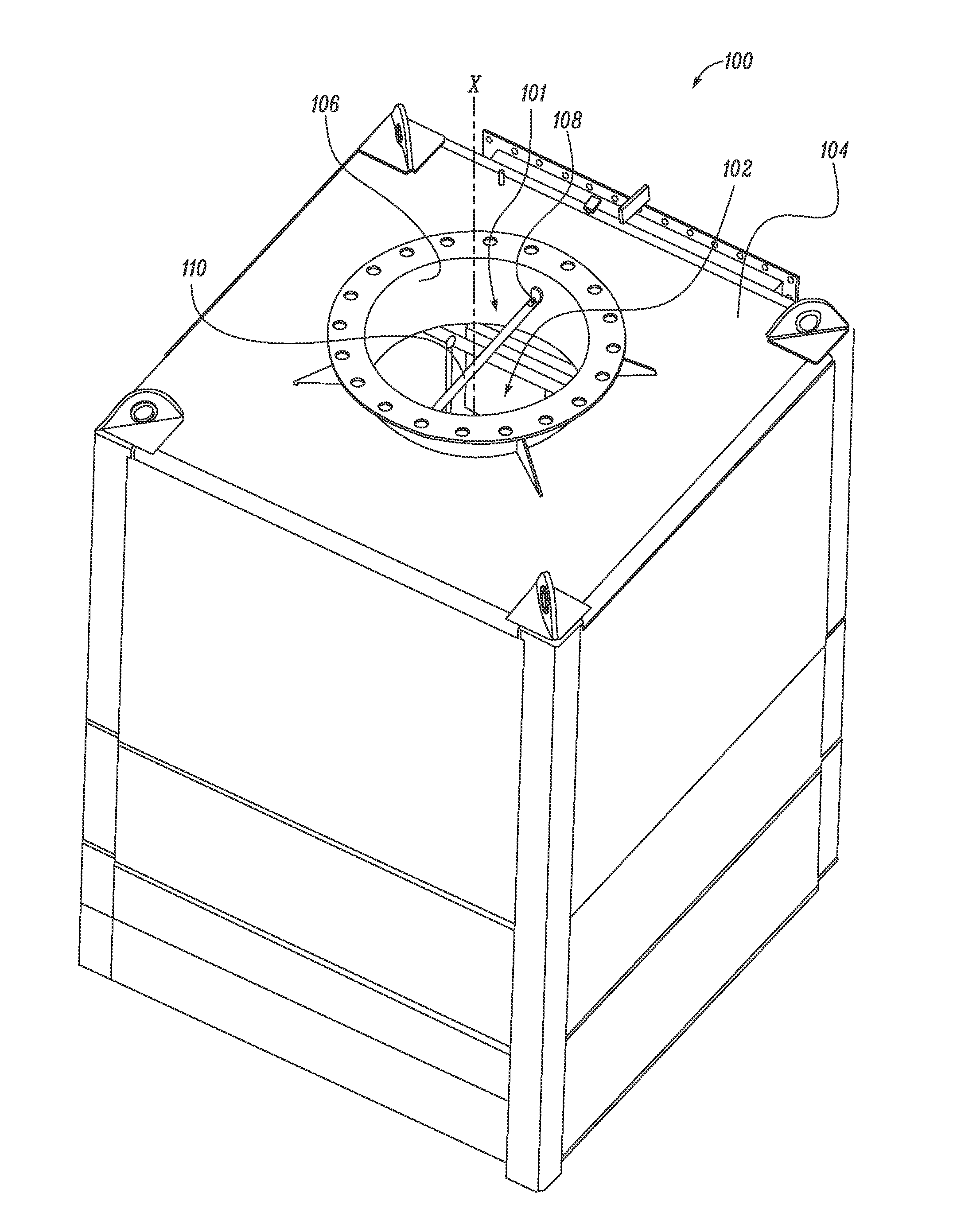
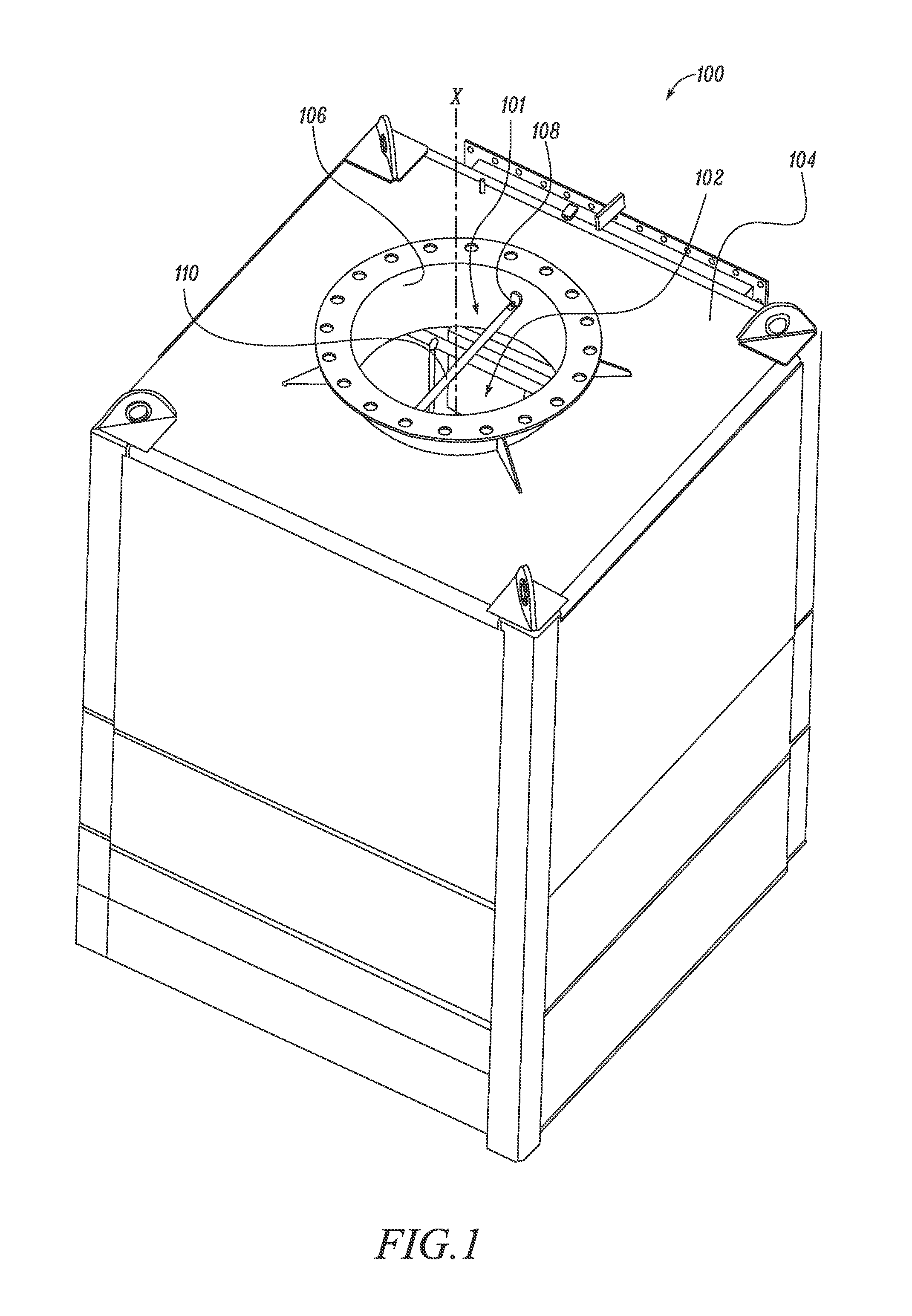
[0013]Wherever possible, the same reference numbers will be used throughout the drawings to refer to the same or the like parts. Referring to FIG. 1, an exemplary exhaust system 100 of an engine (not shown) is illustrated. The exhaust system 100 includes an outlet 101. This outlet 101 is located downstream of a Selective Catalytic Reduction (SCR) catalyst of an aftertreatment system 102 of the engine, with respect to a direction of flow of exhaust gas in the system. The aftertreatment system 102 is enclosed within a housing 104 in the accompanying figures. The aftertreatment system 102 is configured to introduce a reductant into the exhaust gas flow of the engine. The exhaust gas flow may contain one or more constituents, such as, carbon monoxide (CO), sulfur dioxide (SO2), nitrogen oxides (NOx) and other similar compositions in a gaseous state. In one embodiment, the aftertreatment system 102 may introduce the reductant to reduce and / or convert an amount of NOx present in the exhau...


PUM

PropertyMeasurementUnit
widthaaaaaaaaaa
concentrationaaaaaaaaaa
surface areaaaaaaaaaaa

Abstract

A system including a sampling flute is provided. The sampling flute defines a conduit therein. The sampling flute includes a plurality of holes configured for allowing passage of an exhaust gas flow therethrough. The system also includes a hood provided on the sampling flute. The hood is configured to enclose a nitrogen oxide sensor therein. The hood includes an inlet in fluid communication with the sampling flute. The hood also includes an outlet positioned opposed to the inlet. The hood is configured to cause the exhaust gas flow to impact a side of the nitrogen oxide sensor.

Description

TECHNICAL FIELD[0001]The present disclosure relates to a system and method for sampling of a fluid, and more specifically to a sampling flute for sampling of an exhaust gas flow.BACKGROUND[0002]A nitrogen oxide sensor (NOx sensor) may be positioned at various locations in an engine system, in order to measure a concentration of nitrogen oxide in exhaust gas flowing through the system. For example, the NOx sensor may be present downstream of an outlet of a Selective Catalytic Reduction (SCR) catalyst with respect to a direction of flow of the exhaust gas.[0003]A reading provided by the NOx sensor is based on a portion of the exhaust gas flowing thereover. However, in some situations, the NOx sensor may contact with a relatively small portion of the exhaust gas flow due to its position within an exhaust conduit of the exhaust system. Known designs include providing a sampling element within an exhaust outlet in order to direct a portion of the exhaust gas flow over the NOx sensor, suc...

Claims


Application Information

Patent Timeline
Patent Type & Authority Applications(United States)
IPC IPC(8): G01N1/22F01N3/20
CPCF01N3/2066G01N1/22G01N1/2252G01N33/0037F01N13/008F01N2240/20F01N2560/026Y02A50/20Y02T10/12
Inventor DENIS, ANDREW M.BAIG, MIRZA P.DESHMUKH, SACHIN S.SPAETH, ERIC P.
Owner CATERPILLAR INC
Why Eureka
Try Eureka