

Coil and manufacturing method for same, and reactor
a manufacturing method and coil technology, applied in the direction of magnets, inductances, magnetic bodies, etc., can solve the problems of difficult to remove from molds, difficulty in removing coils from molds, and self-melting layer on the surface of wires, so as to reduce the difficulty of removing coils and reduce the number of steps in manufacturing coils
- Summary
- Abstract
- Description
- Claims
- Application Information
AI Technical Summary
Benefits of technology
Problems solved by technology
Method used
Image

Examples
first embodiment
1. First Embodiment
[0060]A first embodiment of the present invention is described in detail below, with reference to FIGS. 1 through 5.
(1) Constitution
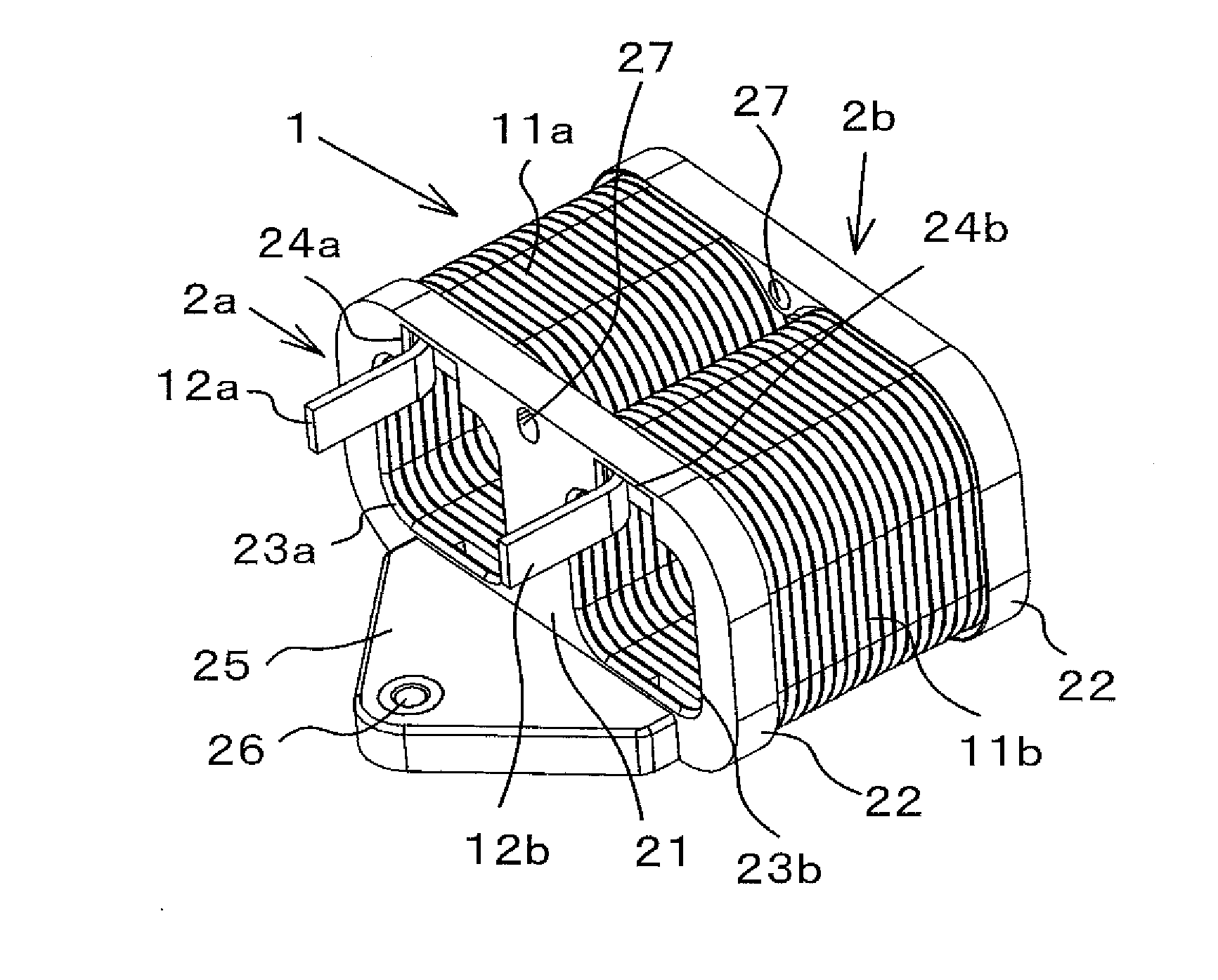
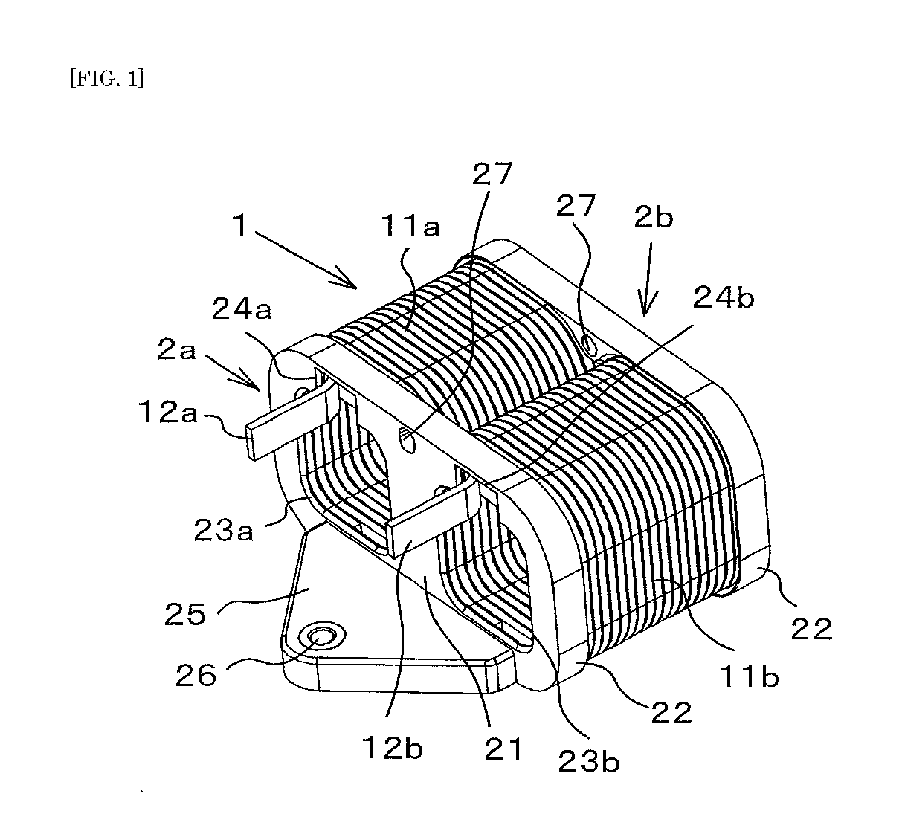
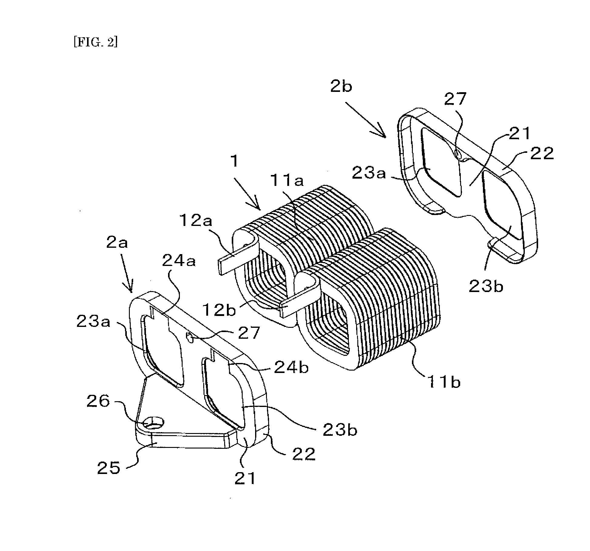
[0061]An edgewise coil of the present embodiment is constituted by a cylindrical coil unit 1 in which flat wire on a surface of which a self-melting layer is formed is wound in a square shape, and first and second resin members (called coil-side resin members) 2a and 2b which are mounted on both axial-direction end faces of the coil unit 1. Resin ordinarily used in self-melting layers can be used as the resin constituting the self-melting layer, but a resin in which a inciting film comprising a main epoxy agent and a curing agent is in a semi-cured state can be used. The coil-side resin members 2a and 2b comprise materials which have greater heat resistance than the adhesion temperature of the self-melting layer, such as PPS (polyphenylsulfide) resin, for example.
[0062]The coil unit 1 is provided with a pair of left and right winding ...
second embodiment
2. Second Embodiment
[0079]A second embodiment of the present invention is described with reference to FIGS. 6 to 8. Parts which are the same as in the first embodiment are given the same reference numerals and description thereof is omitted.
[0080]As shown in FIG. 6, in the present embodiment, the first coil-side resin member 2a is provided with the plate-shaped end plate 21 only to the bottom portion of the end faces of the left and right winding portions 11a and 11b. Edge places 22a and 22b which enter the left and right winding portions 11a and 11b are provided to the end plate 21. The bracket 25, which is platform-shaped and extends horizontally in the opposite direction as the edge places 22a and 22b but at the same height as the edge places 22a and 22b, is provided to the end plate 21. The bracket 25 is fitted into part of the core-side resin member 6a (bottom portion) when constituting the reactor, and is therefore shaped so as to cover the bottom face of the core.
[0081]When m...
third embodiment
3. Third Embodiment
[0085]A third embodiment is described with reference to FIGS. 9A and 9B. As disclosed in Japan Patent Application Publication No. 2009-261086 A, in the edgewise coil using conventional flat wire adjacent segments of the flat wire are tight against each other with no gaps therebetween, and therefore heat release from between the adjacent segments of the flat wire is difficult, which may cause heat becoming trapped inside the coil. In the present embodiment, as shown in the cross-sectional view in FIG. 9B, protrusions W which protrude from flat wire faces L on inner faces of bends Rat each of the four corners of the winding portions 11a and 11b are formed in the coil unit 1, and adjacent segments of the protrusions W are adhered to one another by the self-melting layer. Specifically, the protrusions W are adhered by the self-melting layer to the protrusions W in adjacent segments of the flat wire where the wound flat wire has adjacent segments. Therefore, adjacent s...
PUM
| Property | Measurement | Unit |
|---|---|---|
| heat resistance | aaaaa | aaaaa |
| pressure | aaaaa | aaaaa |
| self-melting | aaaaa | aaaaa |
Abstract
Description
Claims
Application Information