Voltage Detection Device and Equalization Device

a voltage detection and equalization device technology, applied in secondary cell servicing/maintenance, instruments, electrochemical generators, etc., can solve the problems of reducing the efficiency of use or charging excessively, unable to detect the failure of lpf, and reducing the cost of operation. cost

Active Publication Date: 2015-06-11
YAZAKI CORP
View PDF2 Cites 19 Cited by
  • Summary
  • Abstract
  • Description
  • Claims
  • Application Information

AI Technical Summary

Benefits of technology

[0014]As described above, in the first aspect, the failure detector detects whether or not the lowpass filters are in failure by comparing detection values detected by the first voltage detector, that is, detection values detected via the lowpass filters, with detection values detected by the second voltage detector, that is, detection values detected without passage through the lowpass filters. Therefore, a failure including a leak failure of a lowpass filter can be detected.
[0015]In the second aspect, the switching unit switches the voltage to be input to the Analog-to-Digital converter among voltages of the unit batteries that are supplied via the lowpass filters and voltages of the unit batteries that are supplied without passage through the lowpass filters. Therefore, the first voltage detector and the second voltage detector can be formed by a single Analog-to-Digital converter and hence cost reduction can be attained.
[0016]In the third aspect, whether each equalization switch is turned on or off can be judged on the basis of a voltage at the connecting point of the corresponding discharge resistor and the equalization switch. Therefore, whether a circuit for on / off-controlling the equalization switches can also be detected.

Problems solved by technology

In such battery assemblies, if a variation occurs between the voltages across the pairs of ends of the respective unit batteries, they may be reduced in the efficiency of use or charged excessively.
However, in the above conventional technique, when an LPF fails, it may be impossible to detect the LPF failure depending on its type.
More specifically, in the case of a failure that the output voltage of an LPF decreases markedly in a short time due to, for example, breaking of a resistor of the LPF that results in its opening, the LPF failure can be detected on the basis of a detection result of the voltage across the both ends of the unit battery.
On the other hand, in the case of a failure that the output of an LPF decreases gradually over a long time due to, for example, a leak failure of a capacitor, the LPF failure cannot be discriminated clearly from degradation of the characteristic of the unit battery itself and hence it is difficult to detect the LPF failure soon after its occurrence.
Where an LPF failure cannot be detected promptly as in the latter case, a detection value of the unit battery is lower than an actual value until detection of the failure, possibly lowering the efficiency of use of the battery or causing its overcharging.
However, although the device disclosed in JP-A-2012-122856 can detect disconnection of an LPF, it cannot detect a leak failure of a capacitor.

Method used


Image

  • Voltage Detection Device and Equalization Device
  • Voltage Detection Device and Equalization Device
  • Voltage Detection Device and Equalization Device

Examples


Embodiment Construction

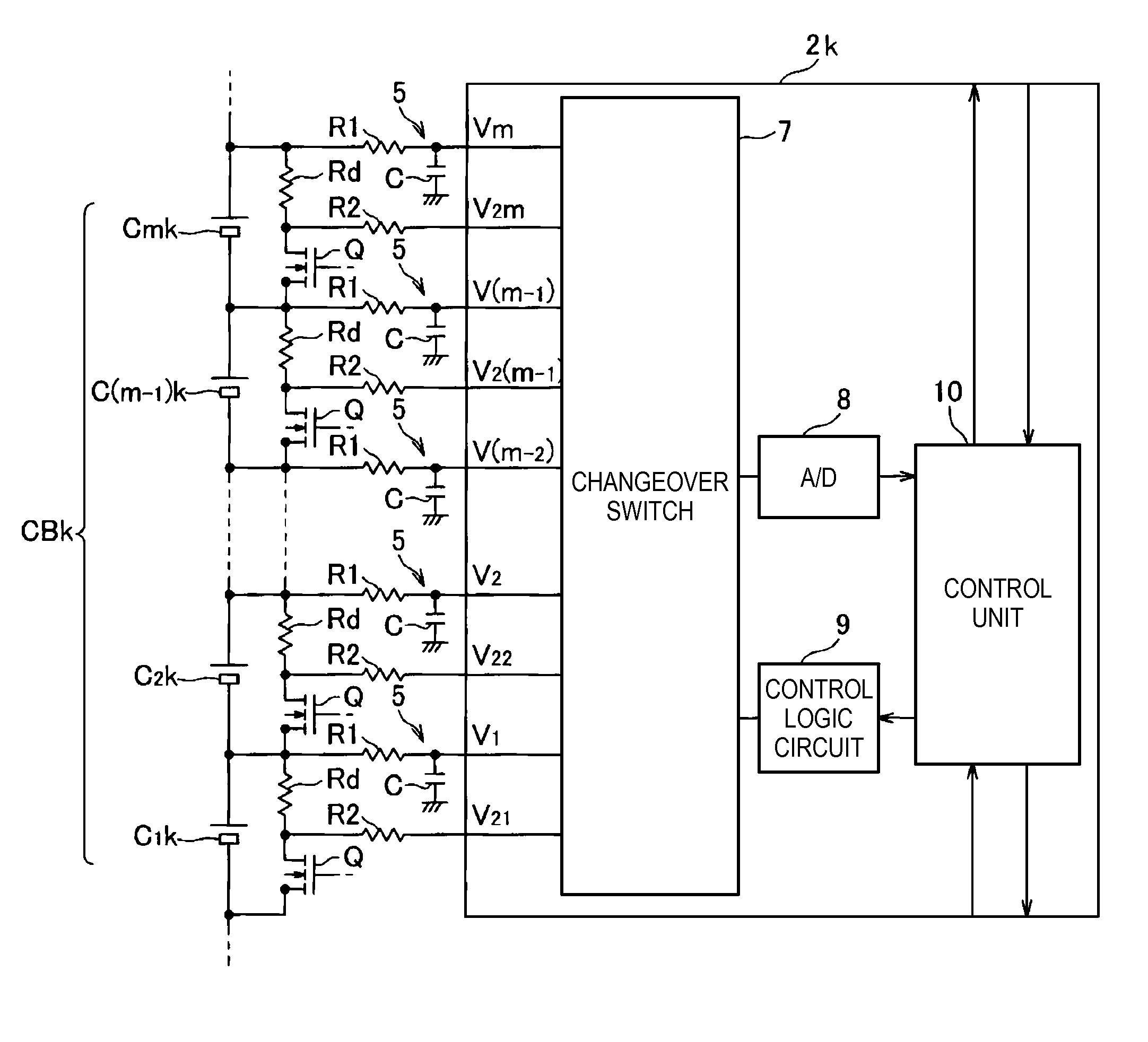
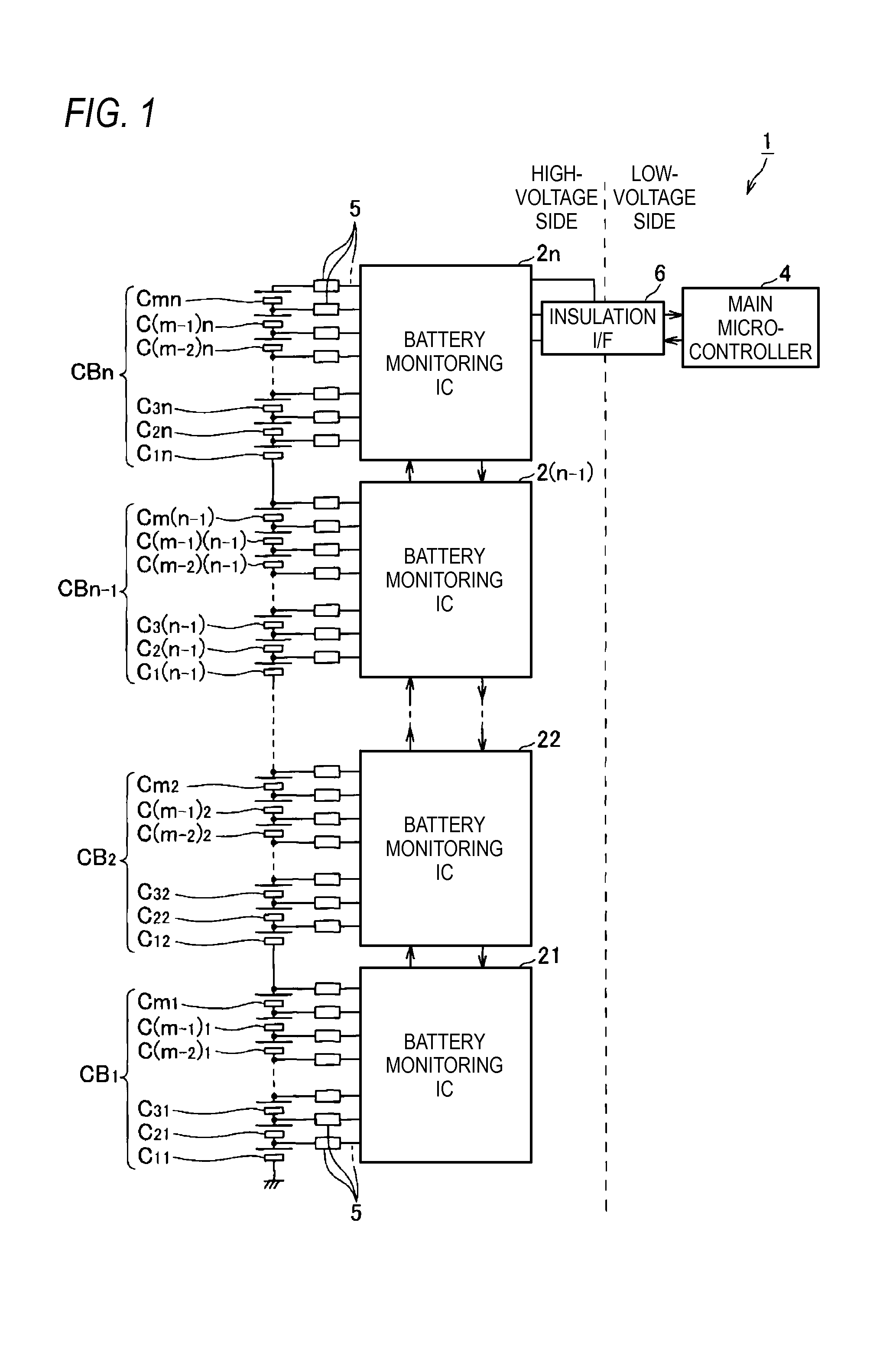
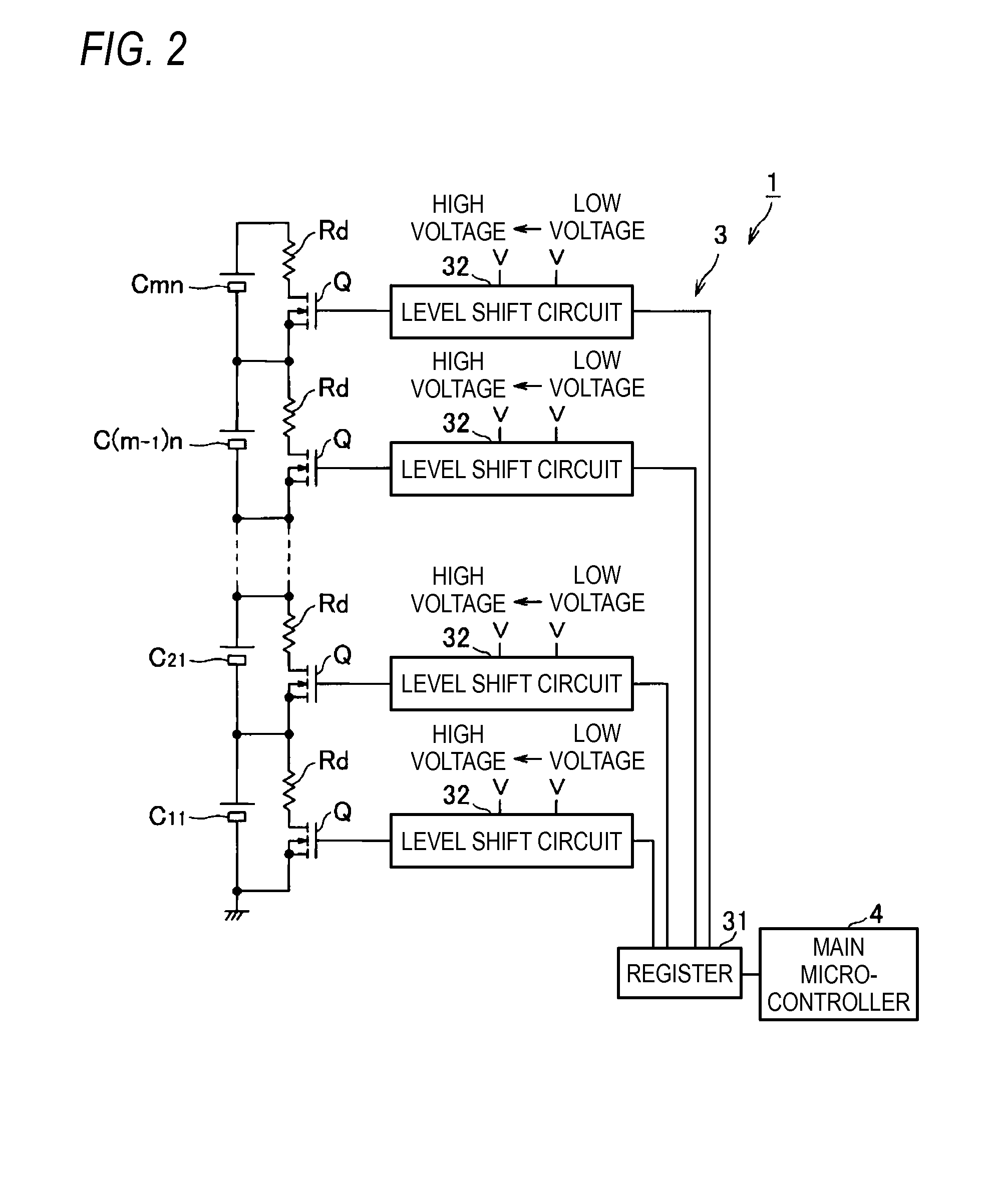
[0021]An embodiment of an equalization device incorporating a voltage detection device according to the present invention will be hereinafter described with reference to FIGS. 1-4. As shown in FIG. 1, an equalization device 1 is a device for equalizing the voltages across pairs of ends of plural unit batteries C11-Cmn that constitute a battery assembly BH and are connected to each other in series. Although in the embodiment each of the unit batteries C11-Cmn is a single secondary battery, it may consist of plural secondary batteries.

[0022]For example, the battery assembly BH is used as a power source of an electric motor of a hybrid electric vehicle which employs, as running drive sources, an engine and the electric motor (neither of which are shown). Not only is the electric motor connected to the both ends of the battery assembly BH as a load when necessary but also an alternator or the like (not shown) is connected to the both ends of the battery assembly BH as a charger when nec...


PUM


Abstract

A voltage detection device for detecting a voltage across the both ends of each of plural unit batteries which are connected to each other in series, includes lowpass filters which are connected to the respective unit batteries, a first voltage detector detects a voltage across the both ends of each of the unit batteries that is supplied via the corresponding lowpass filter, a second voltage detector which detects a voltage across the both ends of each of the unit batteries that is supplied without passage through the corresponding lowpass filter, and a failure detector which detects whether the lowpass filter is in failure by comparing detection value detected by the first voltage detector with a detection value detected by the second voltage detector.

Description

CROSS REFERENCE TO RELATED APPLICATIONS[0001]This application is a continuation of PCT application No. PCT / JP2013 / 075267, which was filed on Sep. 19, 2013 based on[0002]Japanese Patent Application (No. P2012-208480) filed on Sep. 21, 2012, the contents of which are incorporated herein by reference.BACKGROUND OF THE INVENTION[0003]1. Field of the Invention[0004]The present invention relates to a voltage detection device and an equalization device. More particularly, the invention relates to a voltage detection device and an equalization device which detect a voltage across the both ends of each of plural unit batteries that are connected to each other in series.[0005]2. Description of the Related Art[0006]Battery assemblies mounted in, for example, hybrid vehicles and electric vehicles are composed of plural unit batteries that are connected to each other in series. A high voltage of 200 V, for example, appears between their both ends and generated power is supplied to a drive motor....

Claims


Application Information

Patent Timeline
Patent Type & Authority Applications(United States)
IPC IPC(8): H02J7/00G01R19/00G01R31/36H02J7/02
CPCH02J7/0021H02J7/0016G01R35/00H01M10/425H01M10/482G01R31/396G01R19/16542Y02T10/70Y02E60/10
Inventor FUJII, HIRONAOIZAWA, TAKAAKI
Owner YAZAKI CORP
Why Eureka
Try Eureka