Apparatus, system and method for flash heating

a technology of flash heating and apparatus, applied in the field of apparatus, systems and methods for trace particles, can solve the problems of reduced detection quality and consistency, localized hot spots, and large temperature gradients across the heating element surface, and achieve the effect of greater width of electrical flow path

Active Publication Date: 2015-06-11
RAPISCAN SYST INC (US)
View PDF4 Cites 4 Cited by
  • Summary
  • Abstract
  • Description
  • Claims
  • Application Information

AI Technical Summary

Benefits of technology

[0007]In another aspect, a detection system is provided. The detection system includes a housing having a slot configured to receive a sampling device. The detection system also includes a desorber disposed within the housing proximate the slot. The desorber includes a receptacle aligned with the slot, the receptacle configured to receive at least a portion of the sampling device. The detection system further includes at least one heater disposed within the housing external to the receptacle, the at least one heater operable to maintain the receptacle at a first temperature such that, when the sampling device is inserted into the receptacle, a first class of trace particles collected on the sampling device is vaporized. The detection system further includes a flash heater element including a first surface having a central r

Problems solved by technology

However, such rapid flash heating typically causes some locations of the heating element surface to heat more quickly than others, causing localized hot spots and large temperature gradients across the heating element surface.
Collected trace particles on portions of the swab adjacent to relatively hot or cool spots on the h

Method used


Image

  • Apparatus, system and method for flash heating
  • Apparatus, system and method for flash heating
  • Apparatus, system and method for flash heating

Examples


Embodiment Construction

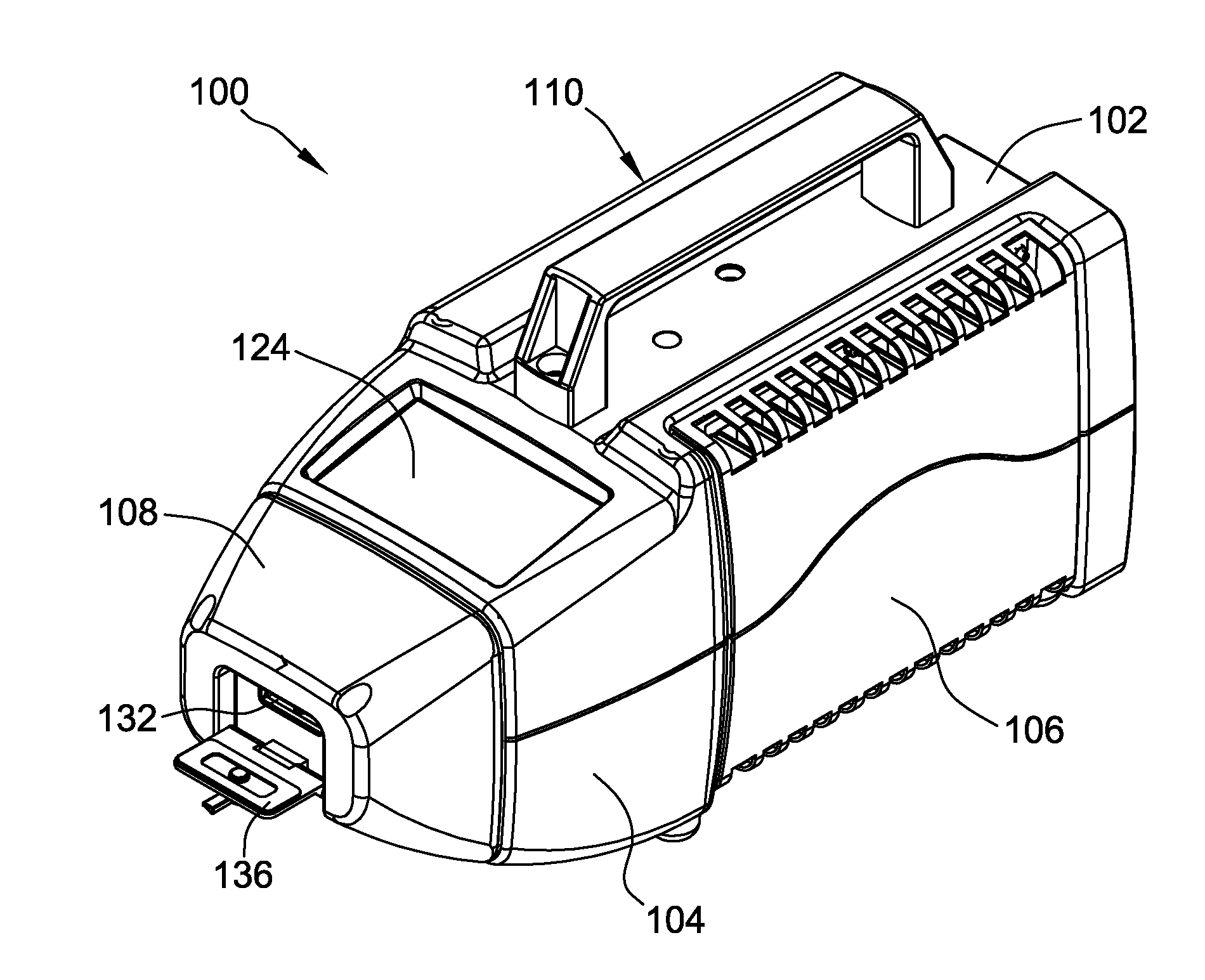
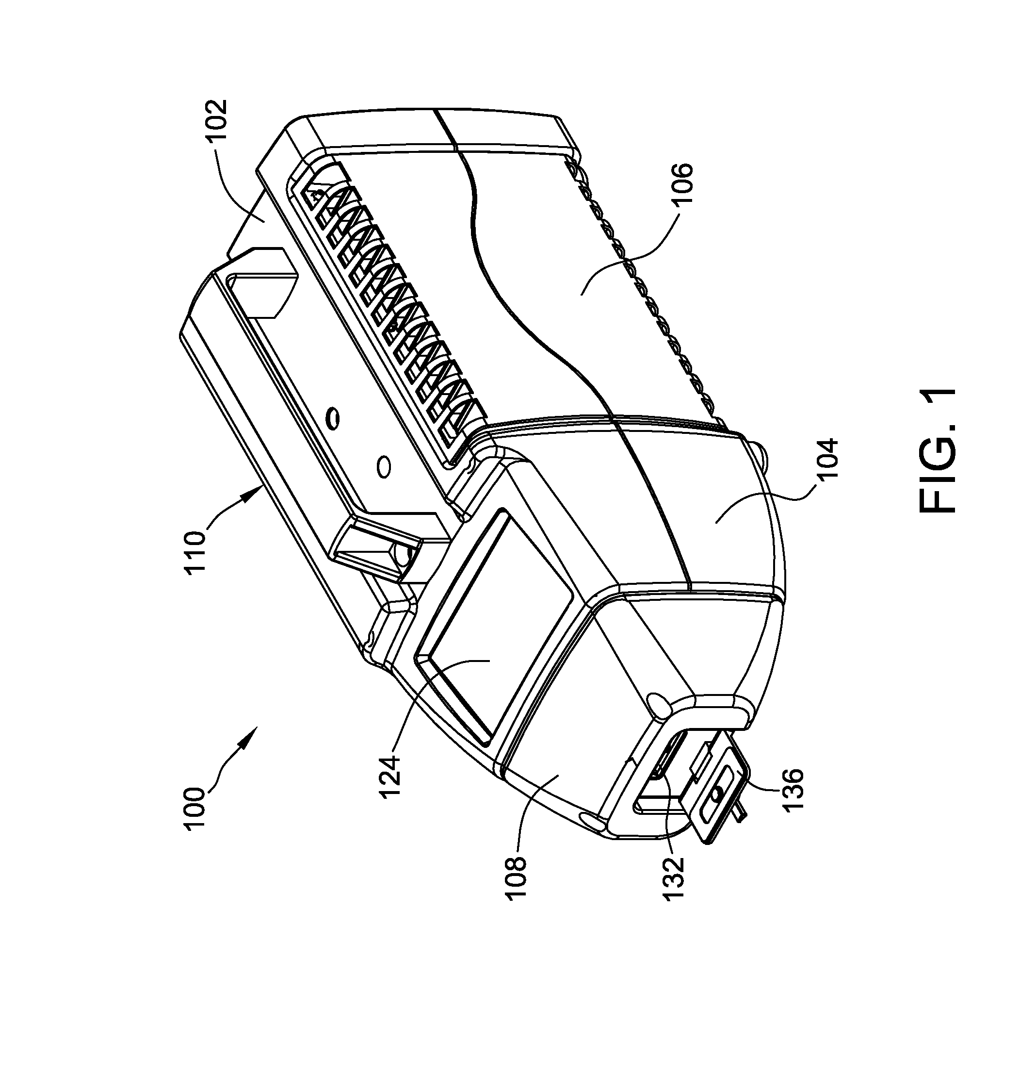
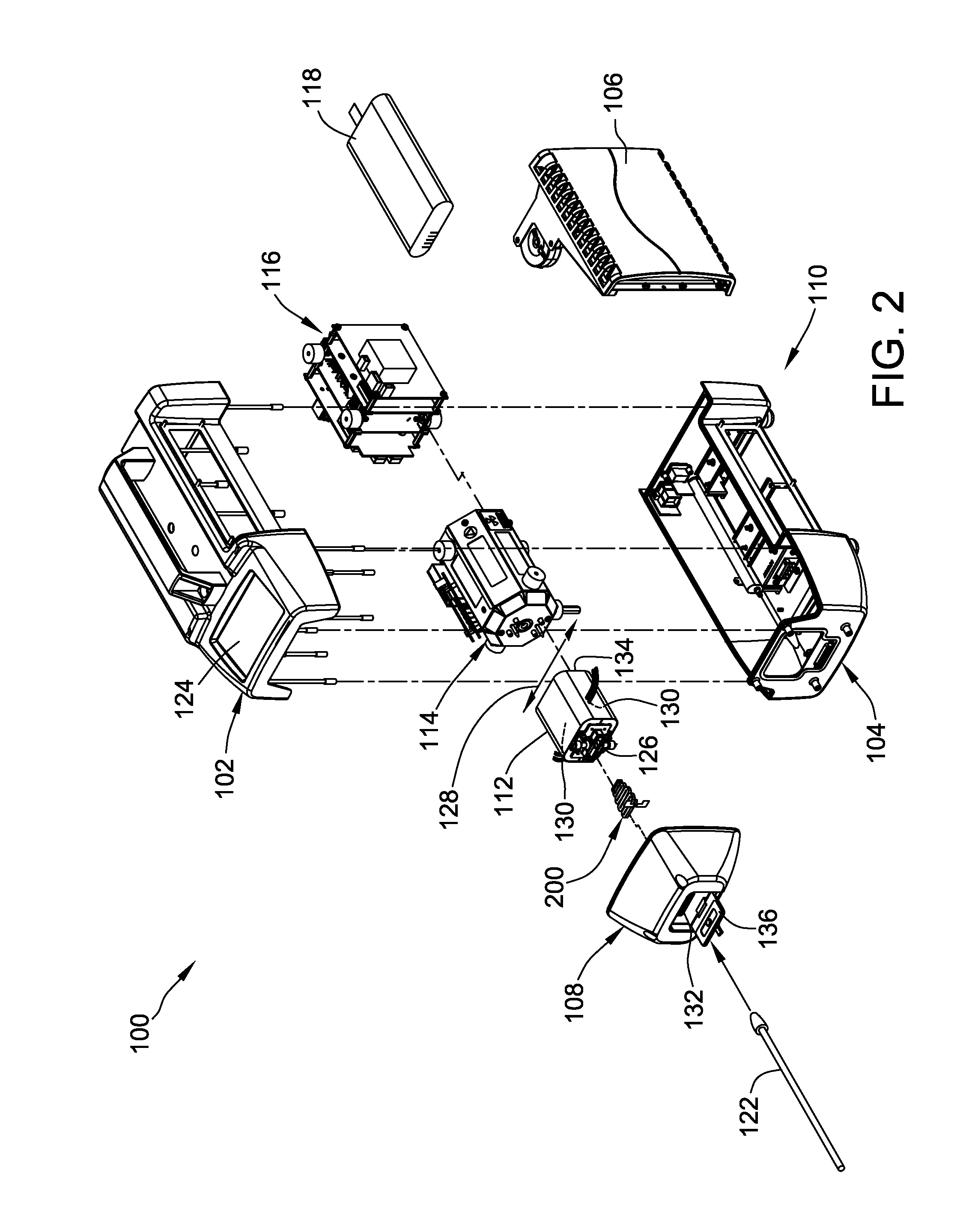
[0017]FIG. 1 is a perspective view, and FIG. 2 is an exploded isometric perspective view, of an exemplary detection system 100 configured to assess the chemical composition and / or biological nature or identity of an unknown substance or material to facilitate identifying potential chemical threats and / or potential biological threats. In the exemplary embodiment, detection system 100 is a portable device. In certain embodiments, detection system 100 may be a handheld device. Alternatively, detection system 100 may be any size.

[0018]With reference to FIG. 1 and FIG. 2, in the exemplary embodiment, detection system 100 includes a top housing assembly 102, a bottom housing assembly 104, a side panel assembly 106, and a front nose assembly 108 configured to be coupled together to form a housing 110 for the system. A door 136 in front nose assembly 108 can be opened to provide access to a slot 132. Disposed within housing 110 are a desorber 112, a detector 114, an electronics assembly 116...


PUM


Abstract

A flash heater element includes a first surface having a central region and an electrical flow path disposed on the first surface. The electrical flow path includes a central portion disposed at least partially within the central region and a peripheral portion disposed peripherally outwardly from the central region. A width of the electrical flow path is greater within at least a portion of the central portion than within the peripheral portion.

Description

BACKGROUND[0001]The field of the invention relates generally to apparatus, systems, and methods for trace detection, and more particularly, to thermal desorption of trace particles to facilitate detection.[0002]Some known detection systems detect trace materials from a swab that is used to sample trace particles from luggage, clothing, or other sources of trace particles. The swab is inserted into a small heated desorber, and the heat from the desorber changes the phase of the sampled trace particles from solid to vapor. The vapor is then channeled into a detector, which analyzes the chemical and / or biological composition of the vapor.[0003]At least some known detection systems incorporate flash heating to vaporize trace particles. Some known flash heaters include one or more planar foil heating elements, each of which is etched to form a serpentine conducting path of essentially constant width. The conductive path is generally designed to have low resistance and a large width relat...

Claims


Application Information

Patent Timeline
IPC IPC(8): H05B1/02H05B3/00G01N33/00
CPCH05B1/0247H05B3/0019G01N33/0011G01N1/02G01N1/2214G01N1/405G01N2001/022G01N2001/028G01N2001/4027H05B3/24H05B2203/003H05B2203/037
Inventor SHAW, BRADLEY DOUGLASGOEDECKE, LYNDON KARL
Owner RAPISCAN SYST INC (US)
Why Eureka
Try Eureka