Process for Producing a Shape Memory Spiral Rotary File

a spiral rotary file and shape memory technology, applied in the direction of shaping tools, teeth capping, teeth nerve/root treatment implements, etc., can solve the problems of less cutting efficiency, less efficient cutting, and more susceptible to breaking within the canal, so as to prevent the damage of the fluting, and reduce the effect of cutting efficiency

Active Publication Date: 2015-06-18
DENTSPLY SIRONA INC
View PDF2 Cites 3 Cited by
  • Summary
  • Abstract
  • Description
  • Claims
  • Application Information

AI Technical Summary

Benefits of technology

[0006]One possibly advantage of the present invention as compared to conventional rotary files is a method for forming a nonlinear file. Another possibly advantage of the present invention as compared to conventional rotary files is a method for forming a nonlinear superelastic file that may be able to change shape and geometry by either expanding or collapsing while shaping a root canal. Also, by shaping the rotary file with this process of using a fixture to shape set a shape memory alloy (e.g., NiTi), it may prevent the fluting from being damaged as well as maintaining the geometry throughout the process of preparing a root canal.
[0007]The advantage to this type of rotary file design as compared to conventional rotary files is in its ability to change shape and geometry by either expanding or collapsing while shaping a root canal. Also, by shaping the rotary file with this process of using a fixture to shape set Nickel Titanium, it prevents the fluting from being damaged as well as maintaining the geometry throughout the process of instrumenting a root canal. U.S. Pat. No. 4,889,487 discusses a method of crimping a file to obtain the desired shape. The problem with crimping a file is that the tool used to crimp will potentially damage the fluting of the file thus making less efficient in cutting. Another issue with crimping a file is that it inherently weakens the file in that crimped area thus making it more susceptible to breaking within the canal. By shape setting the file in a fixture that does not damage the flutes, it allows the file to be stronger and more efficient in cutting as compared to the invention discussed in U.S. Pat. No. 4,889,487.
[0008]The present invention seeks to improve upon prior endodontic instruments by providing an improved process for manufacturing endodontic instruments. In one aspect, the present invention provides a method for manufacturing a nonlinear file (e.g., nonlinear superelastic file) comprising the steps of: providing a file having a shaft and a file axis; providing a first fixture having a first file groove for receiving the shaft, the first file groove being defined by one or more first displacement members; inserting at least one portion of the shaft into the first file groove, the at least one portion of the shaft including a first portion of the shaft; contacting the first portion of the shaft with a first displacement member of the one or more first displacement members such that the first portion of the shaft is displaced from the file axis thereby forming a first offset portion of the shaft, the first offset portion of the shaft and the file axis defining a first file plane; and heating the first offset portion of the shaft while inserted in the first fixture to a temperature from about 200° C. to less than the melting point of the file for a time period from about 1 minute to about 640 minutes to shape-set the first offset portion of the shaft thereby forming a shape-set nonlinear file.
[0009]In another aspect, the present invention contemplates a method for manufacturing a nonlinear file comprising the steps of: providing a linear file having a shaft and a file axis; providing a first fixture having a first mating portion and a second mating portion, each mating portion including a surface, at least one of the surfaces of the first and second mating portions having a first file groove for receiving the shaft, the first file groove extending along a first groove plane that is defined by a first groove axis and one or more first displacement members; inserting a first portion of the shaft into the first file groove so that the file axis along the first portion of the shaft and the first groove axis along the first file groove are generally coaxial; moving at least one of surfaces towards one another so that a first displacement member of the one or more first displacement members displaces the first portion of the shaft from the file axis along the first groove plane thereby forming a first offset portion of the shaft, the first offset portion of the shaft and the file axis defining a first file plane; heating the first offset portion of the shaft while inserted in the first fixture to a temperature from about 200° C. to less than the melting point of the file for a time period greater than 5 minutes but less than about 640 minutes to shape-set the first offset portion of the shaft thereby forming a shape-set nonlinear file; removing the shape-set nonlinear file from the first fixture; providing a second fixture having a first mating portion and a second mating portion, each mating portion including a surface, at least one of the surfaces of the first and second mating portions having a second file groove for receiving a nonlinear shaft of the shape-set nonlinear file, the second file groove having a second groove axis, one or more second displacement members, and a second groove opening that extends along the at least one of the surfaces of the first and second mating portions, the second groove opening generally corresponding to the shape of the first offset portion along the first file plane; inserting a first portion of the nonlinear shaft into the second groove opening; moving at least one of surfaces towards one another so that a first displacement member of the one or more second displacement members displaces the first portion of the nonlinear shaft away from the first file plane thereby forming a second offset portion of the nonlinear file; and heating the second offset portion of the shaft while inserted in the second fixture to a temperature from about 200° C. to less than the melting point of the file for a time period greater than 5 minutes but less than about 640 minutes to shape-set the second offset portion of the nonlinear file thereby forming a shape-set three-dimensional nonlinear file.
[0010]In another aspect, the present invention contemplates a method for manufacturing a nonlinear file comprising the steps of: providing a plurality of files having a shaft and a file axis; providing a first fixture having a first mating portion and a second mating portion, each mating portion including a surface with a plurality of first file grooves having a first groove opening for receiving at least a portion of the shafts of the plurality of files, the first file grooves of the first mating portion surface corresponding to the opposing first file groove of the second mating portion, wherein the groove openings include a base surface having one or more first displacement members; inserting a first portion of the shafts into the first file grooves along the groove openings, wherein the groove openings generally correspond to the shape of the first portion of the shafts along the file axes; moving at least one of surfaces towards one another so that a first displacement member of the one or more first displacement members displaces the first portion of the shafts from the file axes thereby forming a plurality first offset portions of the shafts, each first offset portion of each shaft and each file axis define a first file plane; heating the first offset portions of the shafts while inserted in the first fixture to a temperature from about 200° C. to less than the melting point of the file for a time period from about 5 minutes to about 640 minutes to shape-set the first offset portions of the shafts thereby forming a plurality of shape-set nonlinear files; removing the shape-set nonlinear files from the first fixture; providing a second fixture having a first mating portion and a second mating portion, each including a surface, the surfaces of the first and second mating portions having a plurality of second file grooves with second groove openings extending along the respective surface, the second file grooves of the first mating portion surface corresponding to the opposing first file grooves of the second mating portion, wherein the second groove openings include a base surface having one or more second displacement members; inserting a first portion of a nonlinear shafts of the nonlinear files into the second groove openings; moving at least one of surfaces towards one another so that a first displacement member of the one or more second displacement members of each of the second file grooves displaces the first portion of the nonlinear shafts away from the first file planes thereby forming a second offset portion of the nonlinear files; and heating the second offset portion of the nonlinear shafts while inserted in the second fixture to a temperature from about 200° C. to less than the melting point of the files for a time period from about 5 minutes to about 640 minutes to shape-set the second offset portion of the nonlinear shafts thereby forming a plurality of shape-set three-dimensional nonlinear files.
[0011]In yet another aspect, any of the aspects of the present invention may be further characterized by one or any combination of the following features: wherein the method further comprise the steps of: providing a second fixture having a second file groove for receiving the shaft of the shape-set nonlinear file, the second file groove being defined by one or more second displacement members; inserting the first portion, a second portion, or both of the shaft of the shape-set nonlinear file into the second file groove; contacting the first portion, the second portion, or both of the shaft with a first displacement member of the one or more second displacement members such that the first portion, the second portion, or both of the shaft is displaced from the first file plane thereby forming a second offset portion of the shaft, the second offset portion of the shaft and the file axis defines a second plane that is different from the first plane; and heating the second offset portion of the shaft while inserted in the second fixture to a temperature from about 200° C. to less than the melting point of the file for a time period from about 1 minute to about 640 minutes to shape-set the second offset portion of the shaft thereby forming a shape-set three-dimensional nonlinear file; wherein the shape-set nonlinear file is removed from the first fixture prior to being inserted into the second fixture; wherein the file is formed of a material selected from the group consisting of nickel, titanium, and mixtures thereof; wherein the shape-set nonlinear file is a shape-set nonlinear superelastic file; wherein the first offset portion of the shaft along the first file plane is orientated along the second groove plane of the second file groove, wherein the shape of the first offset portion of the shaft along the first file plane generally corresponds to the shape of the second file groove along the second groove plane; wherein the heating step, the portion of the shaft is heated to a temperature from about 300° C. to about 650° C. for a time period from about 1 minute to about 45 minute to shape-set the portion of the shaft thereby forming the shape-set nonlinear file; wherein the heating step, the portion of the shaft is heated to a temperature from about 350° C. to about 600° C. for a time period from about 3 minutes to about 30 minutes to shape-set the portion of the shaft thereby forming the shape-set nonlinear file; wherein the heating step, the portion of the shaft is heated to a temperature from about 450° C. to about 550° C. for a time period from about 5 minutes to about 20 minutes to shape-set the portion of the shaft thereby forming the shape-set nonlinear file; wherein the heating step, the portion of the shaft is heated to a temperature from about 300° C. to about 650° C. for a time period from about 1 minute to about 45 minute to shape-set the portion of the shaft thereby forming the shape-set nonlinear file; wherein the heating step, the portion of the shaft is heated to a temperature from about 350° C. to about 600° C. for a time period from about 3 minutes to about 30 minutes to shape-set the portion of the shaft thereby forming the shape-set nonlinear file; wherein the heating step, the portion of the shaft is heated to a temperature from about 450° C. to about 550° C. for a time period from about 5 minutes to about 20 minutes to shape-set the portion of the shaft thereby forming the shape-set nonlinear file; further comprising the step of contacting a second portion of the shaft with a second displacement member of the one or more displacement members such that the second portion of the shaft is displaced from the file axis thereby forming a second offset portion of the shaft, wherein the first offset portion of the shaft and the file axis define a first plane and the second offset portion defines a second plane different from the first plane; further comprising the step of contacting a second portion of the shaft with a second displacement member of the one or more displacement members such that the second portion of the shaft is displaced from the file axis thereby forming a second offset portion of the shaft, wherein the first offset portion of the shaft and the file axis define a first plane and the second offset portion defines a second plane different from the first plane; wherein the first offset portion of the shaft along the first file plane is orientated along the second groove plane of the second file groove, wherein the shape of the first offset portion of the shaft along the first file plane generally corresponds to the shape of the second file groove along the second groove plane; wherein the heating step, the first offset portion, the second offset portion, or both is heated to a temperature from about 300° C. to about 650° C. for a time period from about 5 minutes to about 45 minute to shape-set the portion of the shaft thereby forming the shape-set nonlinear file; wherein the heating step, the first offset portion, the second offset portion, or both is heated to a temperature from about 350° C. to about 600° C. for a time period from about 7 minutes to about 30 minutes to shape-set the portion of the shaft thereby forming the shape-set nonlinear file; wherein the heating step, the first offset portion, the second offset portion, or both is heated to a temperature from about 450° C. to about 550° C. for a time period from about 8 minutes to about 20 minutes to shape-set the portion of the shaft thereby forming the shape-set nonlinear file; further comprising the step of contacting a second portion of the shaft with a second displacement member of the one or more first displacement members such that the second portion of the shaft is displaced from the file axis thereby forming a third offset portion of the shaft, wherein the first offset portion and third offset portion of the shaft and the file axis define a first plane and the second offset portion defines a second plane different from the first plane; wherein the first offset portions of the shafts along the first file planes are orientated along the second groove planes of the second file grooves, wherein the shape of the first offset portions of the shafts along the first file planes generally correspond to the shape of the second file grooves along the second groove planes; wherein the heating step, the first offset portions, the second offset portions, or both are heated to a temperature from about 300° C. to about 650° C. for a time period from about 5 minutes to about 45 minute to shape-set the portions of the shafts thereby forming the shape-set nonlinear files; wherein the heating step, the first offset portions, the second offset portions, or both are heated to a temperature from about 350° C. to about 600° C. for a time period from about 7 minutes to about 30 minutes to shape-set the portions of the shafts thereby forming the shape-set nonlinear files; wherein the heating step, the first offset portions, the second offset portions, or both is heated to a temperature from about 450° C. to about 550° C. for a time period from about 8 minutes to about 20 minutes to shape-set the portions of the shafts thereby forming the shape-set nonlinear files; further comprising the step of contacting a second portion of the shafts with a second displacement member of the one or more first displacement members of each first file groove such that the second portions of the shafts are displaced from the file axes thereby forming a third offset portion of the shafts, wherein the first offset portions and third offset portions of the shafts and the file axes define a plurality of first planes and the second offset portions defines a plurality of second planes different from the first planes; or any combination thereof; further comprising the step of providing a handle and attaching the handle to a portion of the nonlinear hand file; or any combination thereof.

Problems solved by technology

Because of the complex curvature of root canals, a variety of unwanted procedural accidents such as ledging, transportation, perforation, or instrument separation, can be encountered in the practice of endodontics.
However, the occurrence of unwanted procedural accidents mentioned above has not been drastically reduced.
The problem with crimping a file is that the tool used to crimp may potentially damage the fluting of the file thus making less efficient in cutting.
Another issue with crimping a file is that it inherently weakens the file in that crimped area thus making it more susceptible to breaking within the canal.
The problem with crimping a file is that the tool used to crimp will potentially damage the fluting of the file thus making less efficient in cutting.
Another issue with crimping a file is that it inherently weakens the file in that crimped area thus making it more susceptible to breaking within the canal.

Method used


Image

  • Process for Producing a Shape Memory Spiral Rotary File
  • Process for Producing a Shape Memory Spiral Rotary File
  • Process for Producing a Shape Memory Spiral Rotary File

Examples


Embodiment Construction

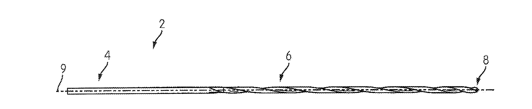
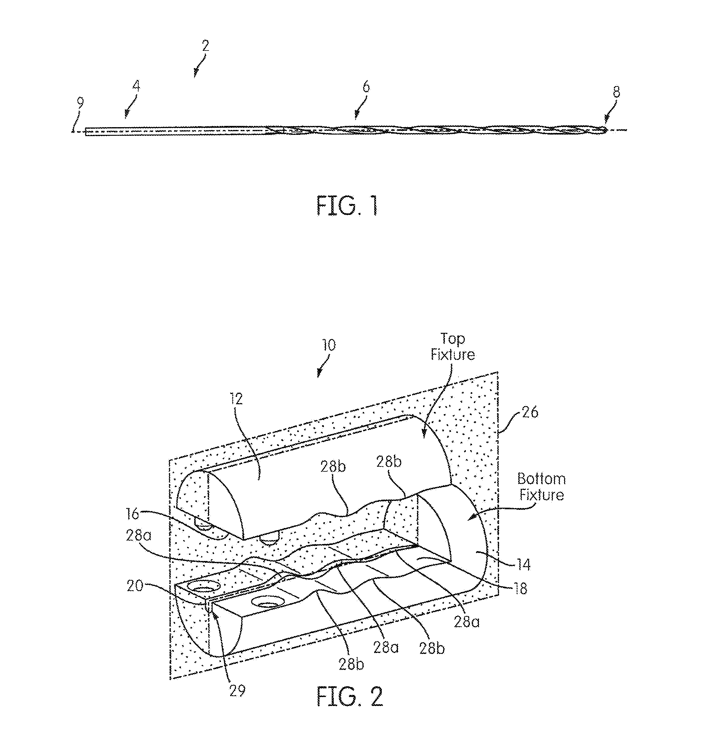
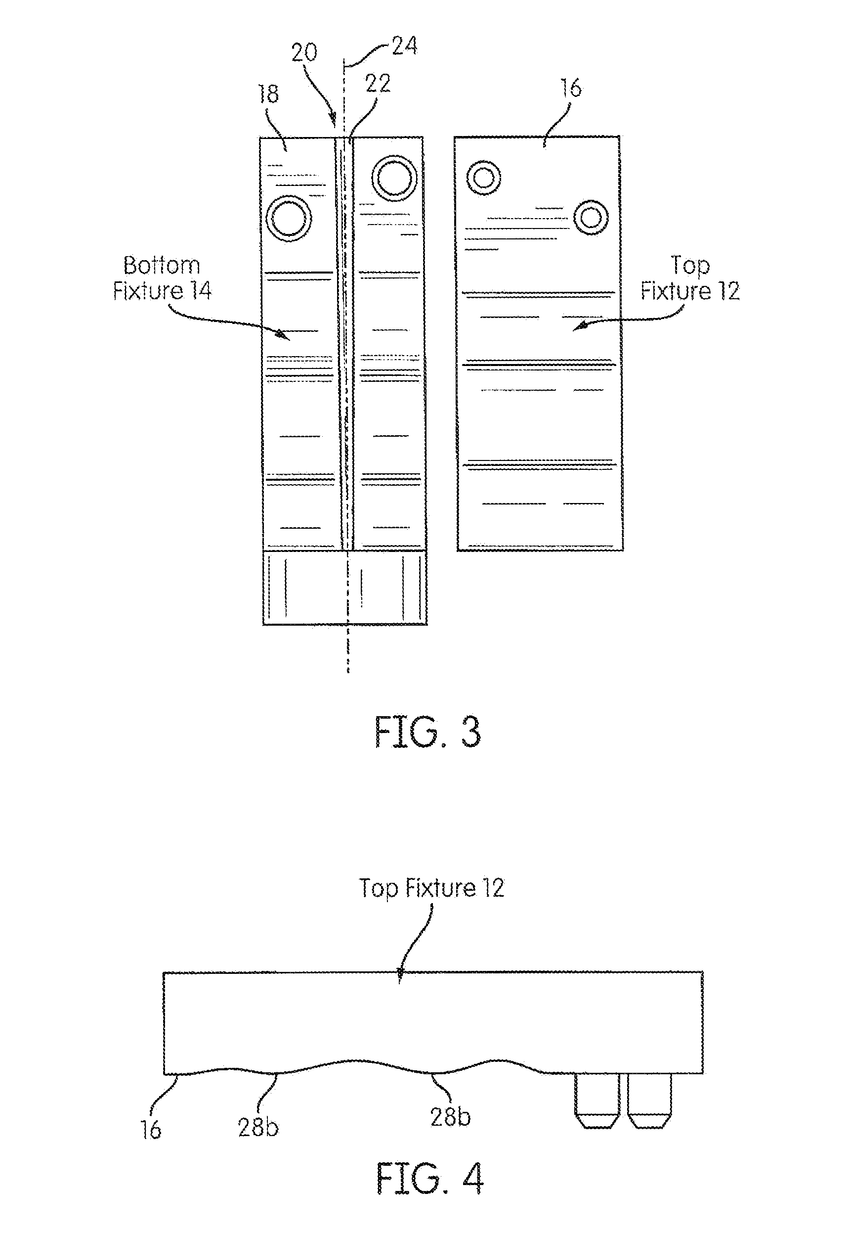
[0030]Previous shape-setting method have been described in co-pending application U.S. Ser. No. 13 / 300,506, which is herein incorporated by reference for all purposes. It is appreciated that the method for forming the shape-setting file generally includes inserting a file into a fixture that includes deformation members for deforming at least one portion of the file. The file 2 may include a handle portion 4, a shaft portion 6 with a tip 8. As seen in FIG. 1. The starting shape of the file is generally linear and extends along a file axis 9. However, other starting shapes are contemplated such as a two-dimensional (2D) shape. The present invention utilizes at least one set fixture (for starting files having a 2D shape) and preferably at least two different shape set fixtures to bend and set the geometry of the file to the desired finished shape (e.g., a three-dimensional (3D) shape. It is appreciated that the fixture(s) is heated to a temperature of at least about 200° C., at least ...


PUM

PropertyMeasurementUnit
temperatureaaaaaaaaaa

Abstract

A method for manufacturing at least one nonlinear file including the steps of deforming at least a portion of a linear file away from a file axis and heat-treating the deformed file to shape-set the nonlinear file.

Description

CROSS-REFERENCE TO RELATED APPLICATIONS[0001]This patent application claims the benefit of and priority to U.S. Provisional Application Ser. No. 61 / 844,980, filed on Jul. 11, 2013, which is herein incorporated by reference for all purposes.FIELD OF INVENTION[0002]The present invention is directed to a method for treating a dental instrument, and specifically to a rotary file useful for shaping and cleaning root canals.BACKGROUND OF THE INVENTION[0003]The endodontic instruments (including files and reamers) are used for cleaning and shaping the root canals of infected teeth. They may be in mode of either rotation or reciprocation in the canal by dentists, either manually or with the aid of dental handpieces onto which the instruments are mounted. Instruments are generally used in sequence (depending on different root canal surgery techniques) in order to achieve the desired outcome of cleaning and shaping. The endodontic instrument is subjected to substantial cyclic bending and torsi...

Claims


Application Information

Patent Timeline
Patent Type & Authority Applications(United States)
IPC IPC(8): A61C5/02
CPCA61C5/023A61C5/42Y10T29/49826B21D37/16B21K5/12B23P15/44
Inventor SHOTTON, VINCENTAMMON, DAN
Owner DENTSPLY SIRONA INC
Why Eureka
Try Eureka