Combustion chamber structure for engine

a combustion chamber and engine technology, applied in combustion engines, engine controllers, cylinders, etc., can solve the problems of insufficient scavenging inside the cavity, difficult to form a homogeneous amount of air-fuel mixture inside, and engine with a very high geometric compression ratio, so as to achieve effective increase the effect of filling efficiency

Active Publication Date: 2015-06-18
MAZDA MOTOR CORP
View PDF10 Cites 20 Cited by
  • Summary
  • Abstract
  • Description
  • Claims
  • Application Information

AI Technical Summary

Benefits of technology

[0012]The advantage of the present invention is that in a high-compression-ratio engine in which compressed self-ignition is performed, the filling efficiency can be effectively increased by performing sufficient scavenging inside the cavity.

Problems solved by technology

However, it is not easy to form a sufficient amount of a homogeneous air-fuel mixture inside the cylinder of an engine with a very high geometric compression ratio, such as described hereinabove.
In particular, where a cavity is formed in the piston crown surface, scavenging inside the cavity becomes insufficient and a sufficient amount of intake air is difficult to supply into the cavity.

Method used


Image

  • Combustion chamber structure for engine
  • Combustion chamber structure for engine
  • Combustion chamber structure for engine

Examples


first embodiment

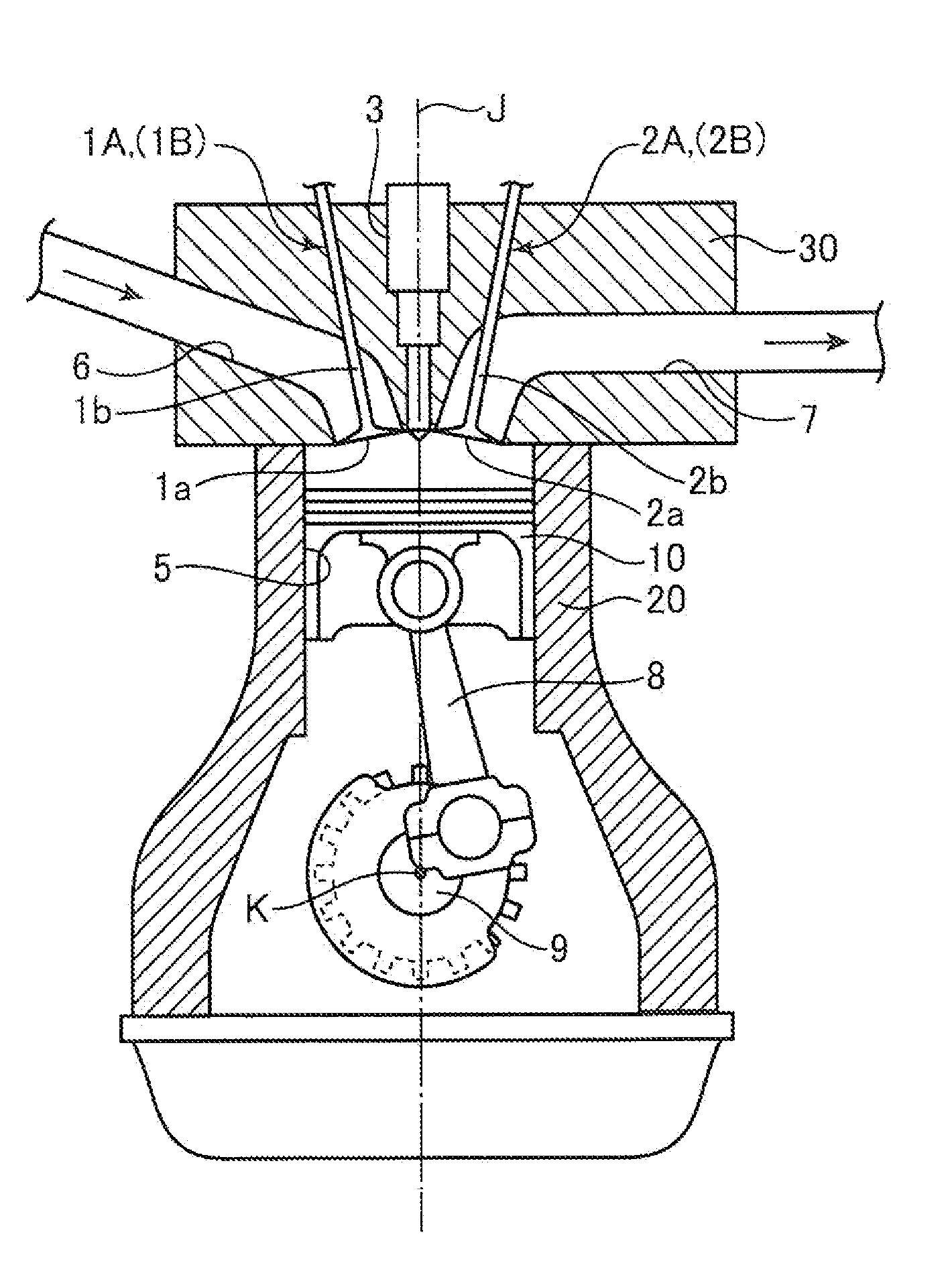
[0041]FIG. 1 shows a schematic configuration of an engine using the combustion chamber structure according to the present invention. The engine shown in the figure is an inline multicylinder gasoline engine to be installed on an automobile and has a cylinder block 20 having a plurality of cylinders 5 (only one thereamong is shown in FIG. 1) arranged side by side in the direction orthogonal to the sheet of this figure, a cylinder head 30 mounted on the cylinder block 20 so as to cover the cylinders 5 from the upper surface, and a piston 10 reciprocatingly inserted into each cylinder 5. A combustion chamber with a volume changing according to the vertical position of the piston 10 is formed above the piston 10. The piston 10 is connected by a connecting rod 8 to a crankshaft 9, and the crankshaft 9 rotates about an axis in response to the reciprocating movement of the piston 10.

[0042]The geometric compression ratio of each cylinder 5, that is, the ratio of combustion chamber volume wh...

second embodiment

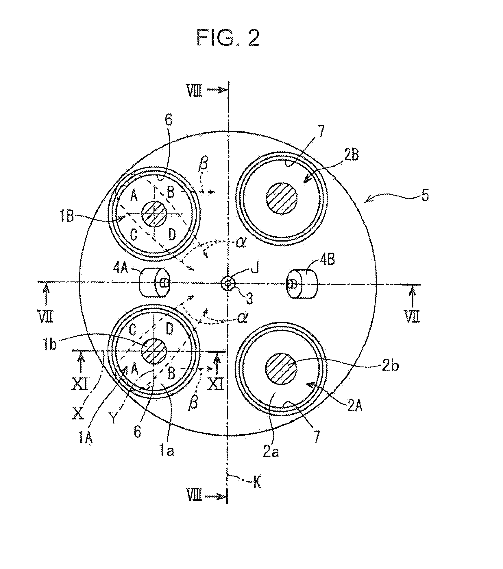
[0080]FIGS. 24 to 26 illustrate the present invention. Here, constituent elements same as those of the above-described embodiment are assigned with same reference numerals and the redundant explanation thereof is herein omitted.

[0081]In the second embodiment, the valve recesses 15A, 15B, 16A, 16B are all formed such as to be capable of accommodating almost all portions of the valve heads 1a, 2a of the intake and exhaust valves, more specifically, the portions other than the portions of the valve heads 1a, 2a that overlap the cavity 11. More specifically, the bottom surfaces of the valve recesses 15A, 15B, 16A, 16B are all formed to be flat, and the height thereof is made as a whole slightly less (for example, by 1 mm) than that of the flat surfaces 10a to 10d on the crown surface of the piston 10.

[0082]FIG. 26 shows the cross-sectional shape of the intake valve 1A and the first valve recess 15A corresponding thereto. As follows from FIG. 26, the valve head 1a of the intake valve1A i...


PUM


Abstract

The axial line of an intake valve is inclined, and a gap between a piston crown surface and a valve head of the intake valve expands in accordance with the approach of the crankshaft axis. A relationship of G2>G1 is fulfilled, where G1 stands for a minimum gap between the lower surface of the cylinder head that is positioned between the intake valve and the exhaust valve facing the intake valve, with the crankshaft axis being interposed therebetween, and the piston crown surface in a top dead center, and G2 stands for a gap at a position that is the closest to the crankshaft axis, from among the gaps between the lower surface of the valve head of the intake valve and the piston crown surface at a center timing of a valve overlap period in which the intake valve and the exhaust valve are both open.

Description

TECHNICAL FIELD[0001]The present invention relates to a combustion chamber structure for an engine performing compressed self-ignition.BACKGROUND ART[0002]Engines using gasoline-based fuel typically employ a spark ignition system in which an air-fuel mixture is forcibly ignited using a sparkplug. Meanwhile, in order to improve significantly the fuel economy, it has recently been suggested to cause compressed self-ignition of the air-fuel mixture (pre-mixing compressed self-ignition) by increasing the geometric compression ratio of the engine to a high compression ratio equal to or higher than 15 while still using the gasoline-based fuel.[0003]Patent Document 1 discloses an engine of a spark ignition system which is not of the compressed self-ignition system, but in which the geometric compression ratio is still increased to a high value equal to or higher than 13. This engine uses a pentroof combustion chamber. In this engine, where Si1 denotes cross-sectional areas of the combustio...

Claims


Application Information

Patent Timeline
Patent Type & Authority Applications(United States)
IPC IPC(8): F02B23/02F02F3/24F02F1/22
CPCF02B23/02F02F3/24F02F1/22F02F3/28F02B23/101F02B2023/085F02B2023/102F02B19/04Y02T10/12F02B11/00F02B23/08F02B23/10
Inventor TODA, TADATOMOWASADA, MITSUNORIHASHIGUCHI, TADASUYOUSO, TAKASHINAGATSU, KAZUHIRO
Owner MAZDA MOTOR CORP
Why Eureka
Try Eureka