
System and method for permittivity distributions with transit time and dispersion tomography

a technology of permittivity and tomography, which is applied in the field of system and system method for noncontact measurement of material properties, can solve the problems of no imagery, insufficient detail needed for substantial material property identification, and inability to determine specific properties of various materials. time-of-flight alone does not provide the level of detail needed for substantial material property identification, and achieves rapid and non-invasive measurement of material properties. , the effect of improving the characterization of material properties

Inactive Publication Date: 2015-06-18
BAYLOR UNIVERSITY
View PDF3 Cites 2 Cited by
  • Summary
  • Abstract
  • Description
  • Claims
  • Application Information

AI Technical Summary

Benefits of technology

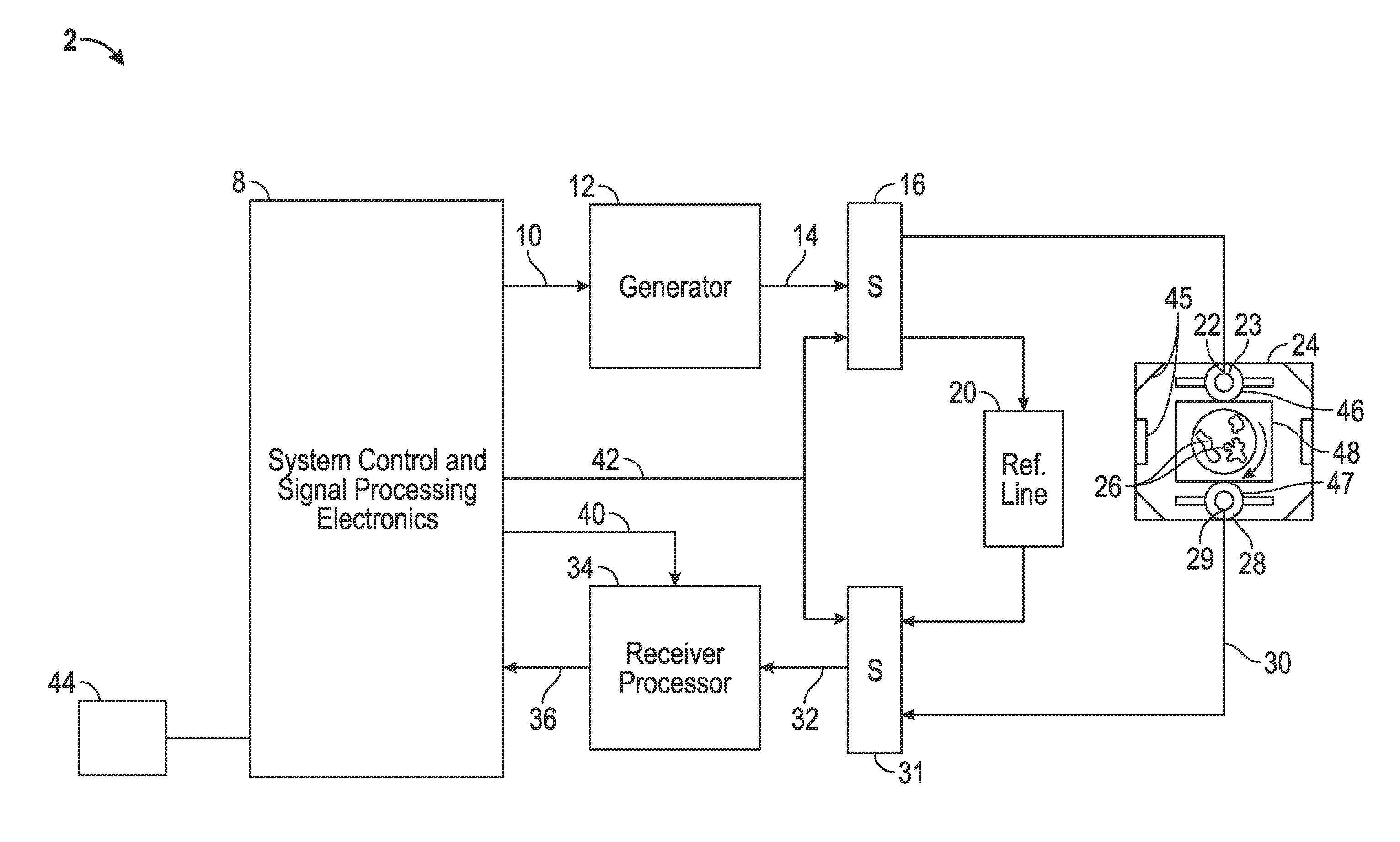
The patent describes an electromagnetic sensor system and method that can quickly and non-invasively measure the properties of materials using EM energy signals. By measuring the dispersion of energy signals over a wide range of frequencies, including second and higher order moments, the system can provide a better understanding of the material's properties. The sensor can create a three-dimensional image of the material based on the results of processed pulses through the object being measured. Overall, this technology allows for faster, more accurate characterization of materials.

Problems solved by technology

While others have used time-of-flight measurements for measuring permittivity, time-of-flight alone does not provide a determination of specific properties for various materials.
Despite the advances in tomography and knowledge of such processing, the imagery is nominal, time consuming, expensive, and has not provided a level of detail needed for substantial material property identification and imaging.

Method used


Image

  • System and method for permittivity distributions with transit time and dispersion tomography
  • System and method for permittivity distributions with transit time and dispersion tomography
  • System and method for permittivity distributions with transit time and dispersion tomography

Examples


Embodiment Construction

[0025]The Figures described above and the written description of specific structures and functions below are not presented to limit the scope of what Applicant has invented or the scope of the appended claims. Rather, the Figures and written description are provided to teach any person skilled in the art how to make and use the inventions for which patent protection is sought. Those skilled in the art will appreciate that not all features of a commercial embodiment of the inventions are described or shown for the sake of clarity and understanding. Persons of skill in this art will also appreciate that the development of an actual commercial embodiment incorporating aspects of the present inventions will require numerous implementation-specific decisions to achieve the developer's ultimate goal for the commercial embodiment. Such implementation-specific decisions may include, and likely are not limited to, compliance with system-related, business-related, government-related and other...


PUM


Abstract

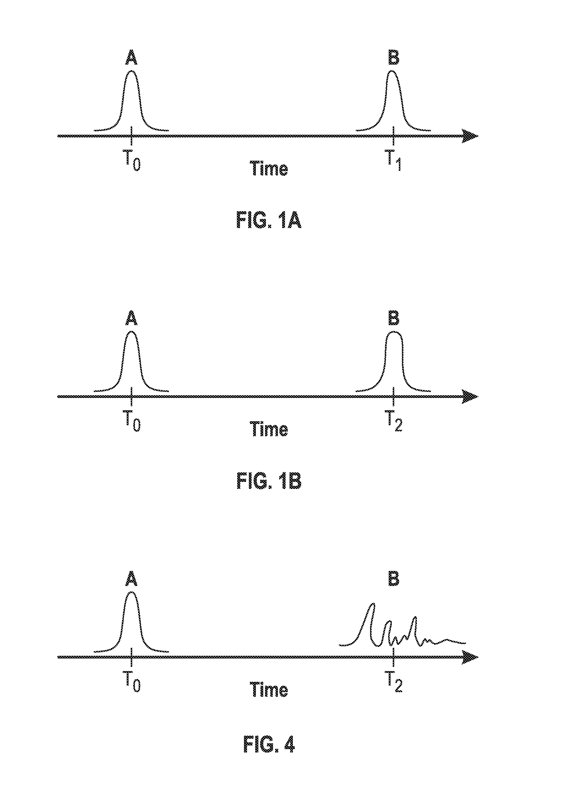
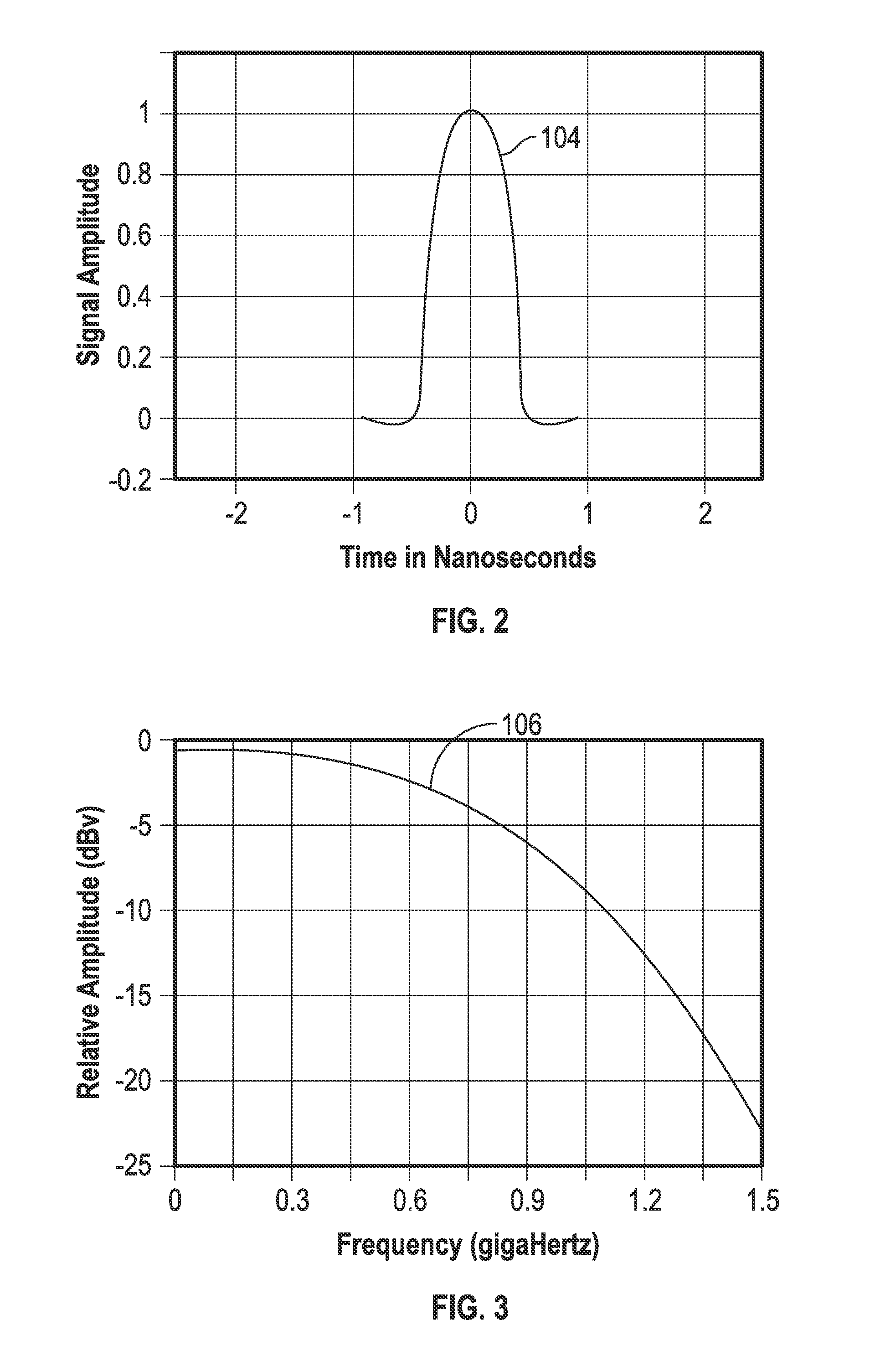
The disclosure provides an electromagnetic (EM) sensor system and method that permits rapid and non-invasive measurement of material properties using measurements of the dispersion of EM energy signals over a wide band of frequencies, including second and higher order moments. The EM energy can be a pulse signal, including an ultra-wide band (“UWB”) pulse signal. A plurality of signals can be incrementally projected through the material in a grid. The grid can generally include a series of projections through the material of an object at different angles. The further analysis of the dispersion characteristics of the EM energy signal provides a measure of added features that assist in improved characterization of the material properties. In at least one embodiment, the results of processed pulses through the object can be used to form a two-dimensional or three-dimensional image of the material for the particular property being measured.

Description

CROSS REFERENCE TO RELATED APPLICATIONS[0001]The present invention is a 35 U.S.C. 371 application of PCT / US2013 / 041847 filed May 20, 2013 claims priority to U.S. Provisional Application Ser. No. 61 / 650,186, filed May 22, 2012, entitled “System And Method For Permittivity Distributions With Transit Time And Dispersion Tomography””, the contents of all of which are incorporated herein by reference.STATEMENT REGARDING FEDERALLY SPONSORED RESEARCH OR DEVELOPMENT[0002]Not applicable.REFERENCE TO APPENDIX[0003]Not applicable.BACKGROUND OF THE INVENTION[0004]1. Field of the Invention[0005]The disclosure relates generally to a system and method for measurement of material properties through complex permittivity distributions of wide band electromagnetic energy. More specifically, the disclosure relates to a system and method for non-contact measurement of material properties with dispersion through materials of short pulses with wide band frequencies.[0006]2. Description of the Related Art[...

Claims


Application Information

Patent Timeline
IPC IPC(8): G01N22/00
CPCG01N22/00
Inventor JEAN, BUFORD RANDALL
Owner BAYLOR UNIVERSITY
Learn More