
Magnetic field sensor and sensing apparatus using the same

a magnetic field and sensor technology, applied in the direction of magnetic measurement, magnetic field measurement using permanent magnets, instruments, etc., can solve the problems of excessive vibration frequency, difficult to form electrodes with complicated shapes, and difficult to measure magnetic fields

Inactive Publication Date: 2015-06-18
SAMSUNG ELECTRO MECHANICS CO LTD
View PDF0 Cites 18 Cited by
  • Summary
  • Abstract
  • Description
  • Claims
  • Application Information

AI Technical Summary

Benefits of technology

The present invention provides a magnetic field sensor and a sensing apparatus that can calculate the magnitude of an external magnetic field by using a piezoelectric driving body and a magnetostrictive layer. The sensor includes a substrate, a piezoelectric driving body formed on the substrate, and a magnetostrictive layer stacked on one portion of the piezoelectric driving body. The sensor can measure the vibration frequency of the piezoelectric driving body and calculate the change in frequency caused by the external magnetic field. The sensor can provide accurate and reliable results even in the presence of external magnetic fields.

Problems solved by technology

Meanwhile, in the structure of the parallel plate capacitor, since the magnitude of the potential difference is not constantly kept when the magnetic field is kept at a predetermined magnitude and the change magnitude of the magnetic field is very slowly generated, it is difficult to measure the magnetic field.
The prior art has a disadvantage in that it is difficult to form the electrode having a complicated shape on a lower surface of the piezoelectric layer and excessively increase the vibration frequency depending on the overtone characteristics of the vibration due to the electrode form.

Method used


Image

  • Magnetic field sensor and sensing apparatus using the same
  • Magnetic field sensor and sensing apparatus using the same
  • Magnetic field sensor and sensing apparatus using the same

Examples


first embodiment

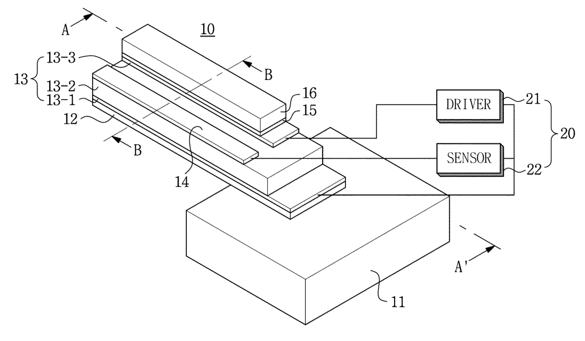
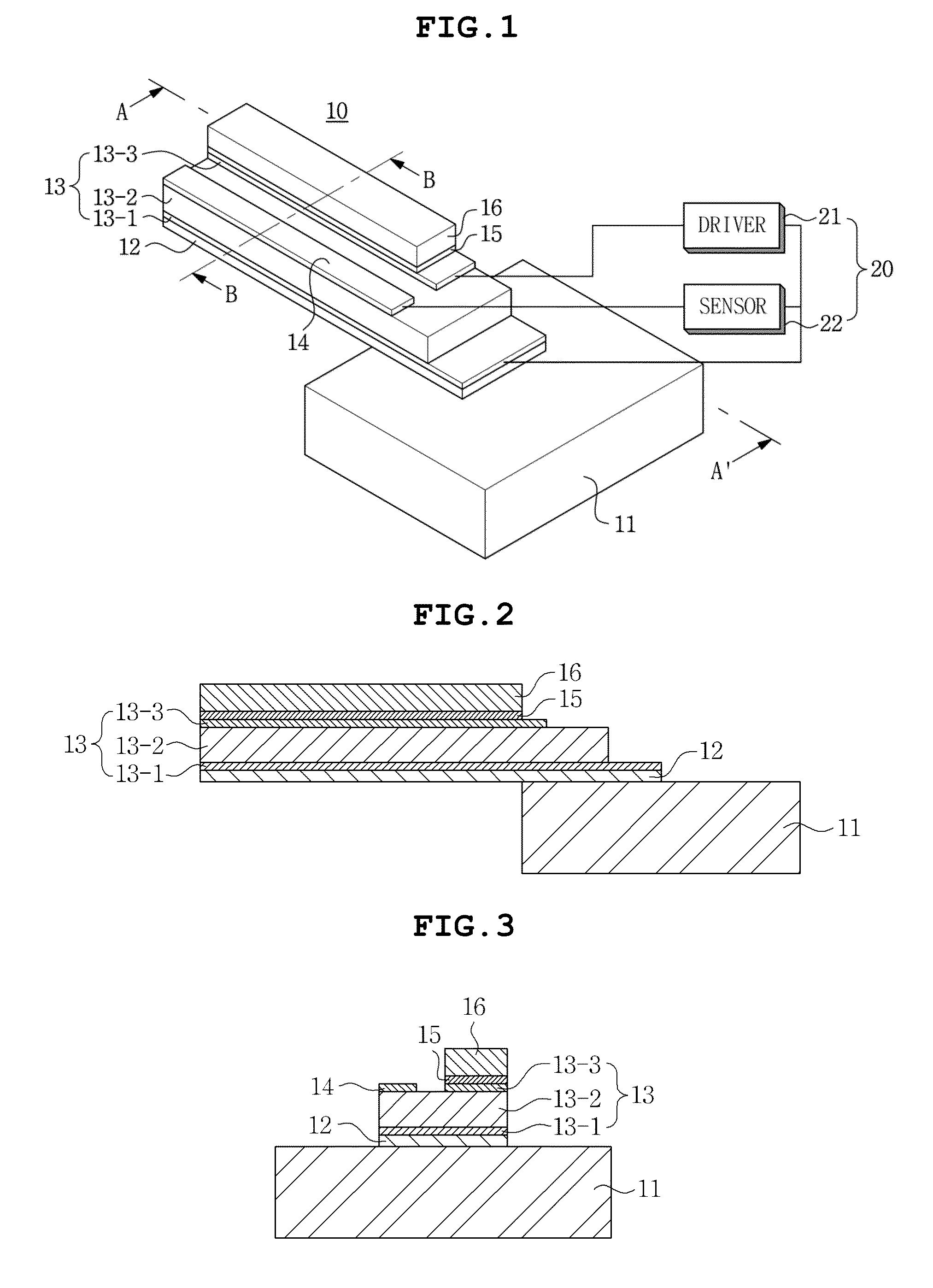
[0124]Meanwhile, according to the present invention, the sensing electrode 14 is separately present by being separated from the second electrode 13-3 of the piezoelectric driving body 13, but cooperates with the first electrode 13-1 by using the second electrode 13-3 as the sensing electrode to measure the voltage of the piezoelectric layer 13-2 and measure the magnitude of the external magnetic layer using the measured voltage.

[0125]Unlike this, the sensing electrode 14 cooperates with the second electrode 13-3 by using the first electrode 13-1 as the sensing electrode to measure the voltage of the piezoelectric layer 13-2 and measure the magnitude of the external magnetic layer using the measured voltage.

[0126]According to the preferred embodiment of the present invention as described above, the external magnetic field may be easily detected by using the simple structure in which the magnetostrictive layer 16 is stacked on the piezoelectric driving body 13.

[0127]Further, according...

second embodiment

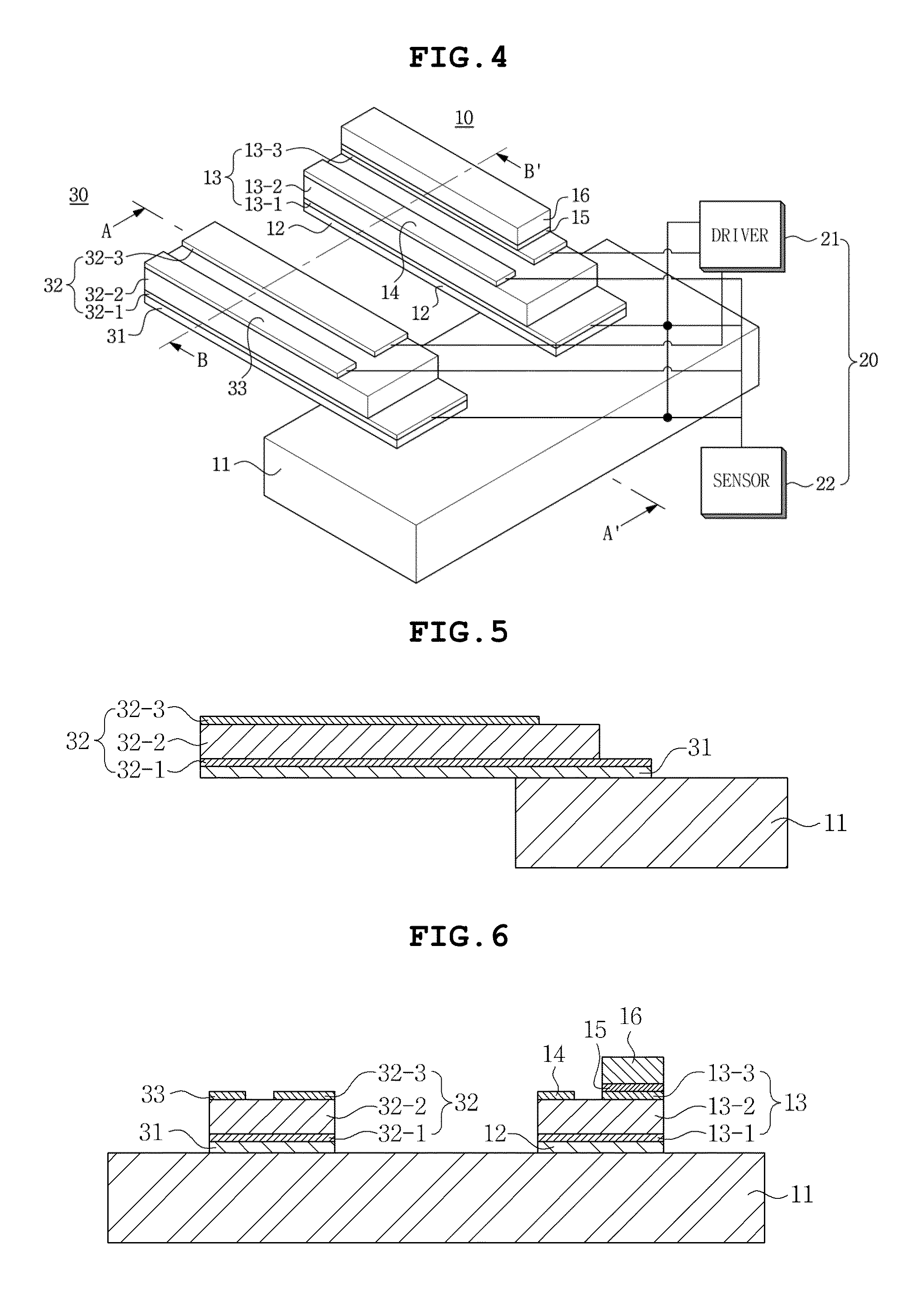
[0164]Meanwhile, according to the present invention, the reference sensing electrode 33 is separately present by being separated from the reference second electrode 32-3 of the reference piezoelectric driving body 32, but cooperates with the first reference electrode 32-1 by using the second reference electrode 32-3 as the sensing electrode to measure the voltage of the reference piezoelectric layer 32-2 and measure the magnitude of the magnetic field using the measured voltage.

[0165]Unlike this, the reference sensing electrode 33 cooperates with the second reference electrode 32-3 by using the first reference electrode 32-1 as the sensing electrode to measure the voltage of the reference piezoelectric layer 32-2 and measure the magnitude of the magnetic field using the measured voltage.

[0166]According to the preferred embodiment of the present invention as described above, the external magnetic field may be easily detected by using the simple structure in which the magnetostrictive...

eleventh embodiment

[0331]Comparing with the sensing apparatus according to the ninth preferred embodiment of the present invention, the sensing apparatus according to the present invention further includes the third magnetic field detection unit 4500 which is a right angle to the first magnetic field detection unit 4100 and the second magnetic field detection unit 4200 and further includes the third reference unit 4510 which is made of the same material and has the same structure as the third magnetic field detection unit 4500, other than the magnetostrictive layer.

[0332]Herein, the third reference unit 4510 may be a right angle to the first reference unit 4110 and the second reference unit 4210.

[0333]Further, the control unit 4400 includes a third driver 4450 which drives the third magnetic field detection unit 4500 and the third reference unit 4510 and a third sensor 4460 which uses the output voltage output from the third magnetic field detection unit 4500 and the third reference unit 4510 to calcu...


PUM


Abstract

Disclosed herein are a magnetic field sensor and a sensing apparatus using the same. The present invention provides a magnetic field sensor including: a magnetic field detection unit which includes a substrate, a piezoelectric driving body formed on the substrate, and a magnetostrictive layer stacked on one portion of the piezoelectric driving body and is vibrated at a vibration frequency changed from a natural frequency in proportion to a magnitude of an external magnetic field; and a control unit which drives the piezoelectric driving body with a constant AC voltage and calculates a magnitude of the external magnetic field from an output voltage output from the magnetic field detection unit, and a sensing apparatus using the same.

Description

CROSS REFERENCE TO RELATED APPLICATION[0001]This application claims the benefit of Korean Patent Application No. 10-2013-0158466, filed on Dec. 18, 2013, entitled “Magnetic Field Sensor and Sensing Apparatus Using Thereof” which is hereby incorporated by reference in its entirety into this application.BACKGROUND OF THE INVENTION[0002]1. Technical Field[0003]The present invention relates to a magnetic field sensor and a sensing apparatus using the same.[0004]2. Description of the Related Art[0005]A magnetic field sensor is configured of a multi-layer composite structure of a piezoelectric layer and a magnetostrictive layer and uses a principle which transfers a change in a structure of the magnetostrictive layer due to an external magnetic field to generate an electrical signal.[0006]According to the prior art, the magnetic field sensor as described above has a simple parallel plate capacitor which has the piezoelectric layer and the magnetostrictive layers attached to both sides of ...

Claims


Application Information

Patent Timeline
Patent Type & Authority Applications(United States)
IPC IPC(8): G01R33/02
CPCG01R33/02G01R33/0286G01R33/038G01R33/18
Inventor KIM, DAE HOPARK, EUN TAE
Owner SAMSUNG ELECTRO MECHANICS CO LTD
Learn More