
Keyless entry system

a keyless entry and key technology, applied in the field of keyless entry systems, can solve the problems of unsatisfactory suppression of the reduction of the lifespan of the battery built in the smart key b>910/b>, the increase in the period of high sensitivity in which the current consumption of the battery increases, and the unnecessarily long period of the high sensitivity in which the battery is consumed, etc., to achieve the effect of not unnecessarily

Active Publication Date: 2015-06-18
ALPS ALPINE CO LTD
View PDF4 Cites 15 Cited by
  • Summary
  • Abstract
  • Description
  • Claims
  • Application Information

AI Technical Summary

Benefits of technology

The present invention provides a keyless entry system for vehicles that can switch detection sensitivity based on the position of a portable device. This system can accurately detect the portable device when it is inside or outside of the vehicle, and automatically lock the vehicle when the portable device is outside. This prevents the battery in the portable device from being unnecessarily consumed and reduces the risk of damage or theft to the vehicle and its equipment. Additionally, the detection sensitivity can be adjusted based on the vehicle's interior or a predetermined distance from the vehicle, which helps to further conserve battery power.

Problems solved by technology

Further, the passive keyless entry system is caused to have an electrical authentication function regarding start-up of an engine, and the engine is prevented from starting when authentication is not successful between a car body and the portable device for high security.
Therefore, there is a problem in that consumption of a battery for a power supply built in the portable device increases.
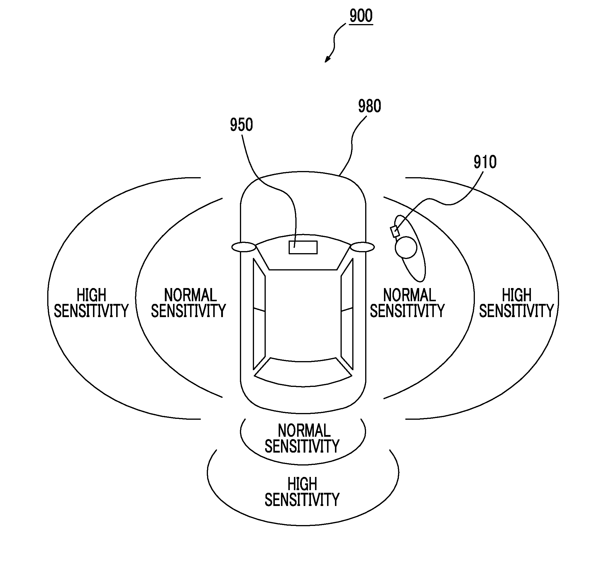
However, there are the following problems with the vehicle control system 900 described in Japanese Unexamined Patent Application Publication No. 2013-083051.
Therefore, a period of the high sensitivity in which current consumption of the battery increases is unnecessarily long.
As a result, reduction of lifespan of the battery built in the smart key 910 cannot be sufficiently suppressed.

Method used


Image

  • Keyless entry system
  • Keyless entry system
  • Keyless entry system

Examples


Embodiment Construction

[0027]Hereinafter, embodiments of the present invention will be described with reference to the drawings.

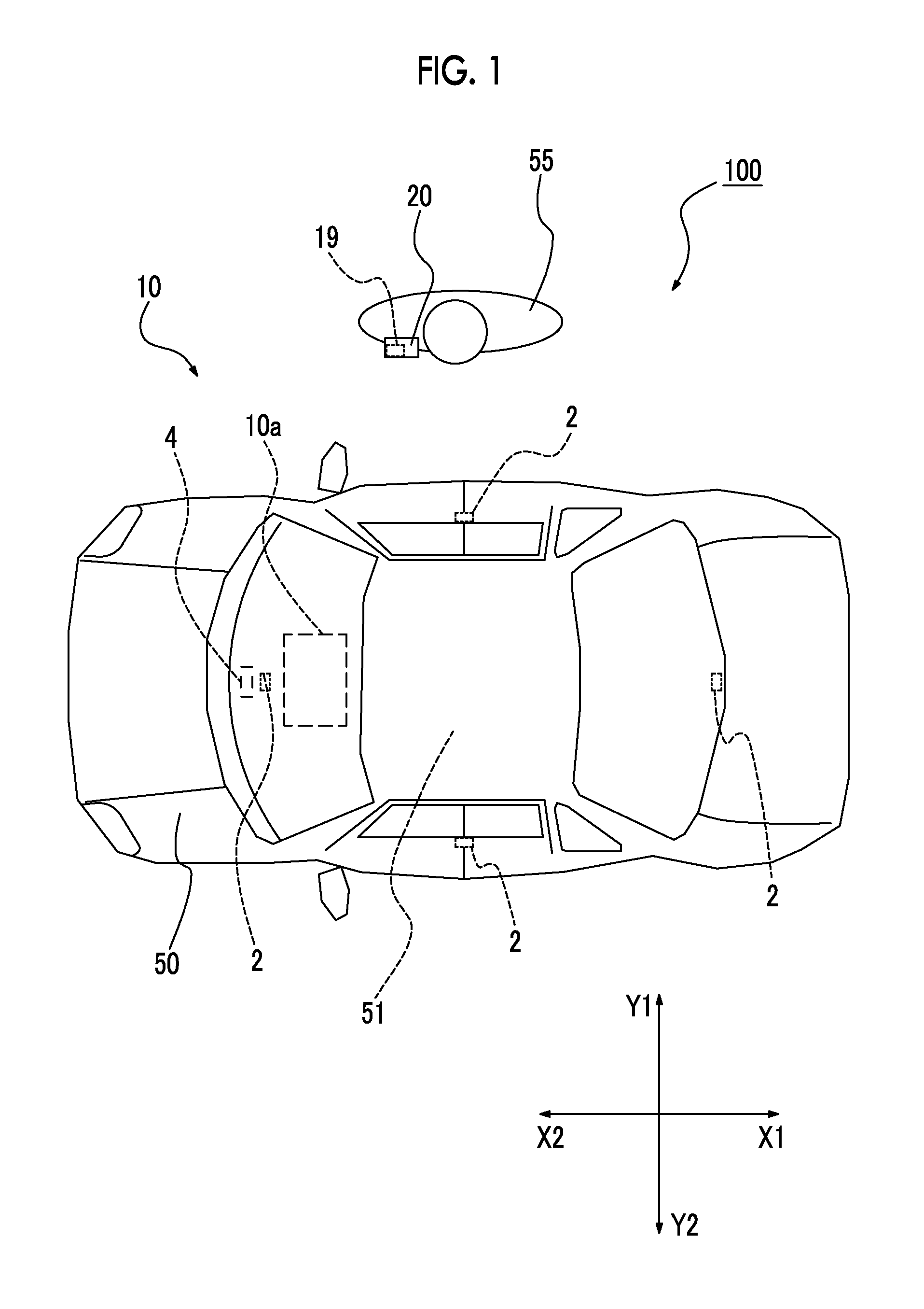
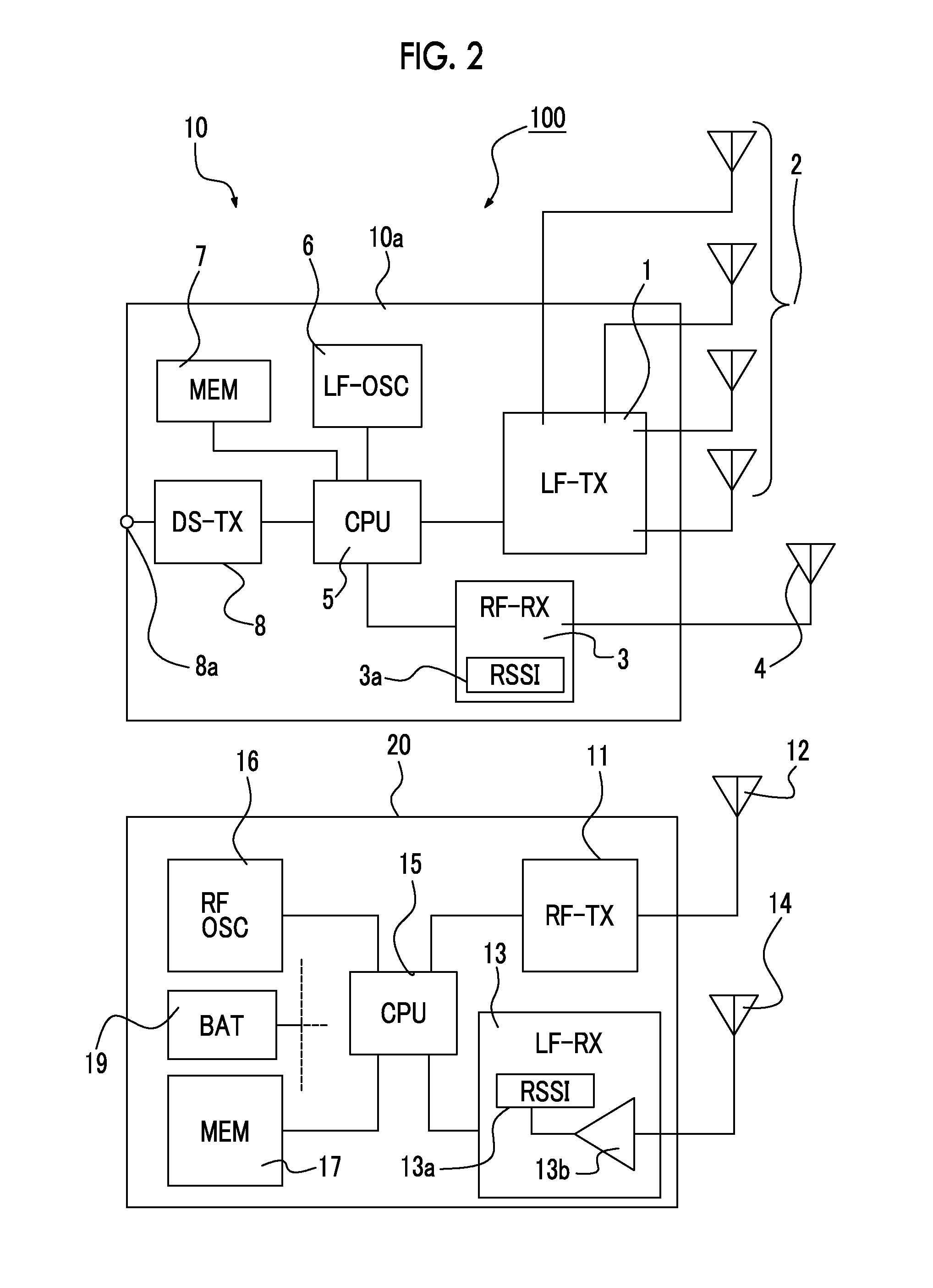
[0028]FIG. 1 is a diagram illustrating a schematic configuration of a keyless entry system 100, and is a plan view when a vehicle 50 including an in-vehicle device 10 and a user 55 carrying a portable device 20 are viewed from the top. The in-vehicle device 10 is mounted on the vehicle 50, and includes an in-vehicle device body 10a, a vehicle-side transmission antenna 2, and a vehicle-side reception antenna 4. In the keyless entry system 100, the vehicle-side transmission antenna 2 includes four antennas located in predetermined positions inside the vehicle 50, and the one vehicle-side reception antenna 4 is arranged near the in-vehicle device body 10a. However, an arrangement of the four vehicle-side transmission antennas 2 and the vehicle-side reception antenna 4 described herein is an example, and other arrangements may be adopted.

[0029]Further, generally, the number of the ve...


PUM


Abstract

In a keyless entry system including an in-vehicle device, and a portable device operated by a built-in battery, a request signal is transmitted from the in-vehicle device to the portable device so that wireless communication is performed between the in-vehicle device and the portable device, the portable device can set first sensitivity that is predetermined sensitivity and second sensitivity that is higher sensitivity than the first sensitivity and at which a detection area for the request signal is wide, as detection sensitivity for detecting the request signal, sets the detection sensitivity to the second sensitivity when determining that the portable device is in the vehicle's interior or within the predetermined distance from the vehicle, and sets the detection sensitivity to the first sensitivity when determining that the portable device is not in or comes to be not in the vehicle's interior or within the predetermined distance from the vehicle.

Description

CLAIM OF PRIORITY[0001]This application claims benefit of Japanese Patent Application No. 2013-257178 filed on Dec. 12, 2013, which is hereby incorporated by reference.BACKGROUND OF THE INVENTION[0002]1. Field of the Invention[0003]The present invention relates to a keyless entry system that locks or unlocks a door of a vehicle by performing wireless communication between an in-vehicle device and a portable device, and more particularly, to a passive keyless entry system having a function of automatically communicating between an in-vehicle device and a portable device.[0004]2. Description of the Related Art[0005]In a moving vehicle such as a car, a door lock is provided in a door of the car so as to prevent the car from being robbed or to prevent the car from being invaded and devices inside the car being damaged when the car is not used. In the related art, locking or unlocking of the door lock is performed by inserting a key for engine start-up into a key hole. However, a so-call...

Claims


Application Information

Patent Timeline
IPC IPC(8): G07C9/00G08C17/02
CPCG08C17/02G07C9/00007B60R25/245G07C9/00G07C9/00309G07C2009/00341G07C2009/0038G07C2009/00547G07C9/20
Inventor YASUI, JUNYAMIYAZAWA, AKIRA
Owner ALPS ALPINE CO LTD
Learn More