Ambient gas flow alarm

a gas flow alarm and ambient technology, applied in the direction of instruments, respirators, measurement of fluid loss/gain rate, etc., can solve the problems of patient not being able to appreciate the gas flow, the gas flow may not be immediately perceptible to the person(s), and the cost of oxygen canisters may be high, so as to enhance the noise generated by the gas flow

Active Publication Date: 2015-06-18
PROMETHEUS MEDICAL INNOVATIONS
View PDF9 Cites 10 Cited by
  • Summary
  • Abstract
  • Description
  • Claims
  • Application Information

AI Technical Summary

Benefits of technology

[0022]In a further contemplated embodiment, the gas flow alarm may include a wall disposed within the main barrel, upstream of the noise generating device, for concentrating the gas flow adjacent to the noise generating device, thereby enhancing the noise generated thereby. The wall may occlude approximately 75-95%, 80-90%, or 85% of an interior diameter of the main barrel.

Problems solved by technology

As also should be apparent to those skilled in the art, it is possible that the flow of gases may be sufficiently low in volume per unit time that the flow of the gases may not be immediately perceptible to the person(s) relying on such gases.
In the case of oxygen, the gas is not toxic to humans, but the waste of oxygen is not preferable, as canisters of oxygen may be expensive to the patients relying on this gas.
In cases where the gases are needed to help sustain the health and life of a person (i.e., the provision of oxygen), there may be instances where the patient does not appreciate if the gas flow has been disconnected accidentally.
Naturally, if the patient were to discover the inadvertent leak of gas at a time where replacement of the gas were not possible or feasible, this might present a significant problem or inconvenience to that person.

Method used


Image

  • Ambient gas flow alarm
  • Ambient gas flow alarm
  • Ambient gas flow alarm

Examples


Embodiment Construction

[0046]The present invention will now be described in connection with one or more embodiments. The discussion of any one embodiment is not intended to be limiting of the present invention. To the contrary, the discussion of various embodiments is intended to illustrate the scope and breadth of the present invention. After reading and understanding the discussion that follows, those skilled in the art may contemplate one or more variations and equivalents to the embodiments discussed herein. Those variations and equivalents are intended to be encompassed by the present invention as if specifically described herein.

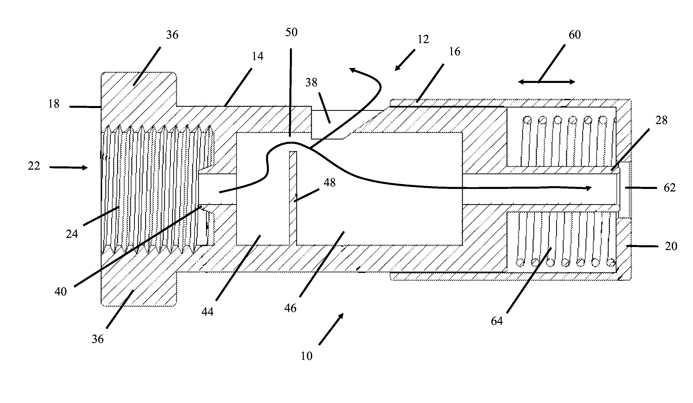
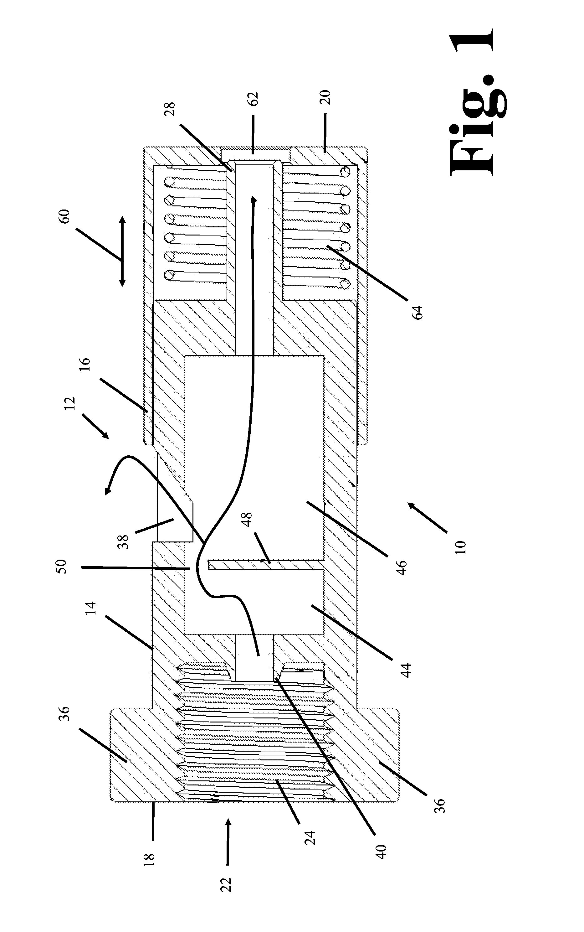
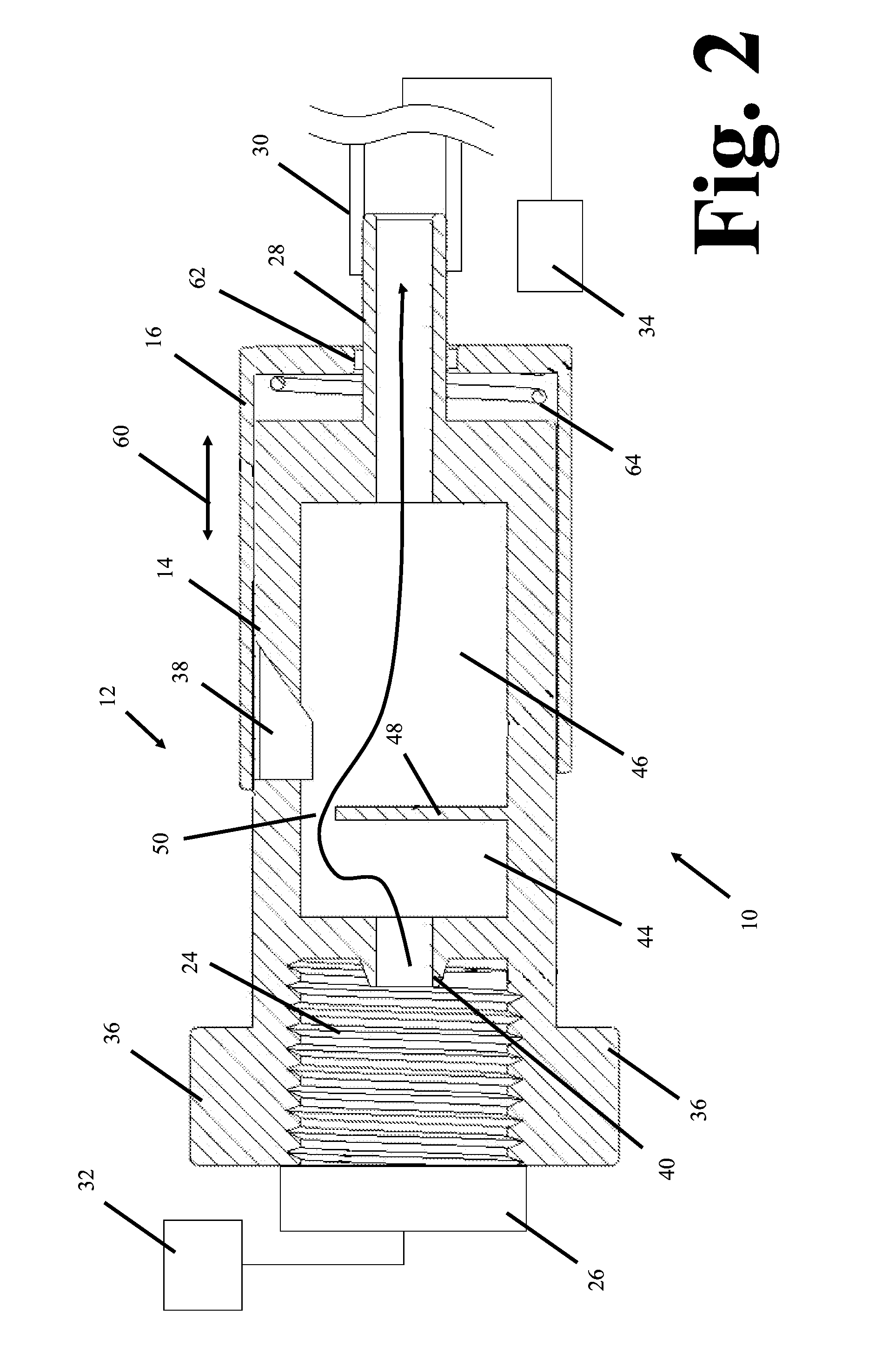
[0047]One embodiment of the alarm 10 of the present invention is illustrated in FIGS. 1-15.

[0048]With reference to FIG. 1, the alarm 10 includes a body 12 with a main barrel 14 onto which a cap 16 is slidably disposed. In the illustrated embodiment, the body 12 has a cylindrical shape. Accordingly, the barrel 14 and the cap 16 also have cylindrical shapes.

[0049]While the ala...


PUM


Abstract

A gas flow alarm includes a main barrel with a proximal end and a distal end. The main barrel defines a gas flow direction from the proximal end to the distal end. A cap is disposed slidingly on the main barrel between a proximal position and a distal position. The proximal position of the cap defines a compressed condition of the gas flow alarm and the distal position of the cap defines an expanded condition of the gas flow alarm. A noise generating device is disposed within the main barrel. The noise generating device is adapted to generate noise from the gas flow when the gas flow alarm is in the expanded condition.

Description

CROSS-REFERENCE TO RELATED PATENT APPLICATION(S)[0001]This International Patent Application relies for priority on U.S. Provisional Patent Application Ser. No. 61 / 658,210, filed on Jun. 11, 2012, the contents of which are incorporated herein in the entirety.FIELD OF THE INVENTION[0002]The present invention relates to an apparatus that generates an alarm in response to leakage of a gas from a source of gases, such as a pressurized gas container. More specifically, the present invention concerns an apparatus that provides an audible alarm should gas leak from the pressurized gas container or should a gas line become disconnected from the pressurized gas container, among other triggering events.DESCRIPTION OF THE RELATED ART[0003]As should be apparent to those skilled in the art, pressurized gases are employed in any of a number of different environments. In one instance, pressurized oxygen is made available to individuals requiring higher concentrations of oxygen to address one or mor...

Claims


Application Information

Patent Timeline
Patent Type & Authority Applications(United States)
IPC IPC(8): G10K5/00G08B21/12
CPCG08B21/12G10K5/00G08B21/14G01M3/26G08B3/02G08B3/06A61M2205/14A61M2205/183A61M16/0051F17D5/005
Inventor DAWSON, RANDY J.
Owner PROMETHEUS MEDICAL INNOVATIONS
Why Eureka
Try Eureka