Digital data transmission apparatus and digital data transmission method

a data transmission apparatus and digital data technology, applied in the direction of instruments, static indicating devices, etc., can solve the problems of electromagnetic wave noise (emi: electro-magnetic interference), image noise (emi), etc., to accelerate the generation of noise, reduce noise, and reduce nois

Inactive Publication Date: 2016-08-09
MITSUBISHI ELECTRIC CORP
View PDF13 Cites 0 Cited by
  • Summary
  • Abstract
  • Description
  • Claims
  • Application Information

AI Technical Summary

Benefits of technology

[0008]For reducing such noise, a transmitter and a receiver for transmitting the digital data need to have complex arithmetic circuits. Japanese Patent Application Laid-Open Nos. 2008-287154 and 2010-210693 are intended to reduce noise (EMI) by performing mathematical operations on digital data in LVDS differential interface or the like, therefore, their transmitters and receivers are provided with complex arithmetic circuits.
[0009]Further, since each of the image signals allocated in a single clock period is temporally compressed and mapped, the frequency of alternation of the High state and the Low state of the digital data on the transmission link is several times that of the clock period. Therefore, the alternation further accelerates the generation of noise emitted as electromagnetic waves.
[0010]The present invention provides a data transmission apparatus and a data transmission method which are capable of having the data transmission apparatus reduce noise generated in transmission links by using a simple configuration, wherein the data transmission apparatus serially transmits a plurality of image signals to an image display device by using digital data which has the image signals allocated.
[0013]According to the above described aspect of the present invention, each of the image signals in the second clock period is cancelled in the case where each of the image signals in the first clock period agrees with corresponding one of the image signals in the second clock period. Therefore, the present invention can reduce noise generated in transmission links only with a simple configuration by transmitting digital data which has the respective cancelled image signals allocated.

Problems solved by technology

The alternation of the High state and the Low state of the digital data disturbs the power saving effect, and the alternation of the High state and the Low state on the transmission link causes noise (EMI: Electro-Magnetic Interference) emitted as electromagnetic waves.
Many of the images are displayed on personal computers and the like in a neutral monochrome color, and, in fact, these images suffer from noise (EMI) caused by the alternation of the High state and the Low state of the digital data on the transmission link.

Method used


Image

  • Digital data transmission apparatus and digital data transmission method
  • Digital data transmission apparatus and digital data transmission method
  • Digital data transmission apparatus and digital data transmission method

Examples


first preferred embodiment

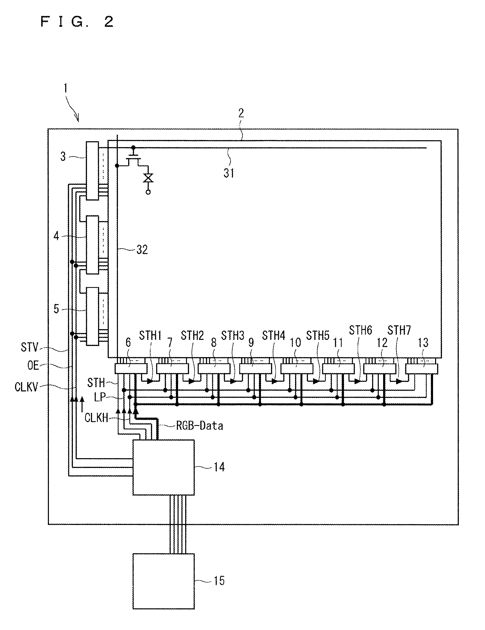
[0043]Although a liquid crystal display device (liquid crystal module) will be exemplified in the preferred embodiment below, the present invention can be applied to a data interface (data transmission apparatus) between a display controller and an image display device including an organic electro-luminescence display device and a plasma display.

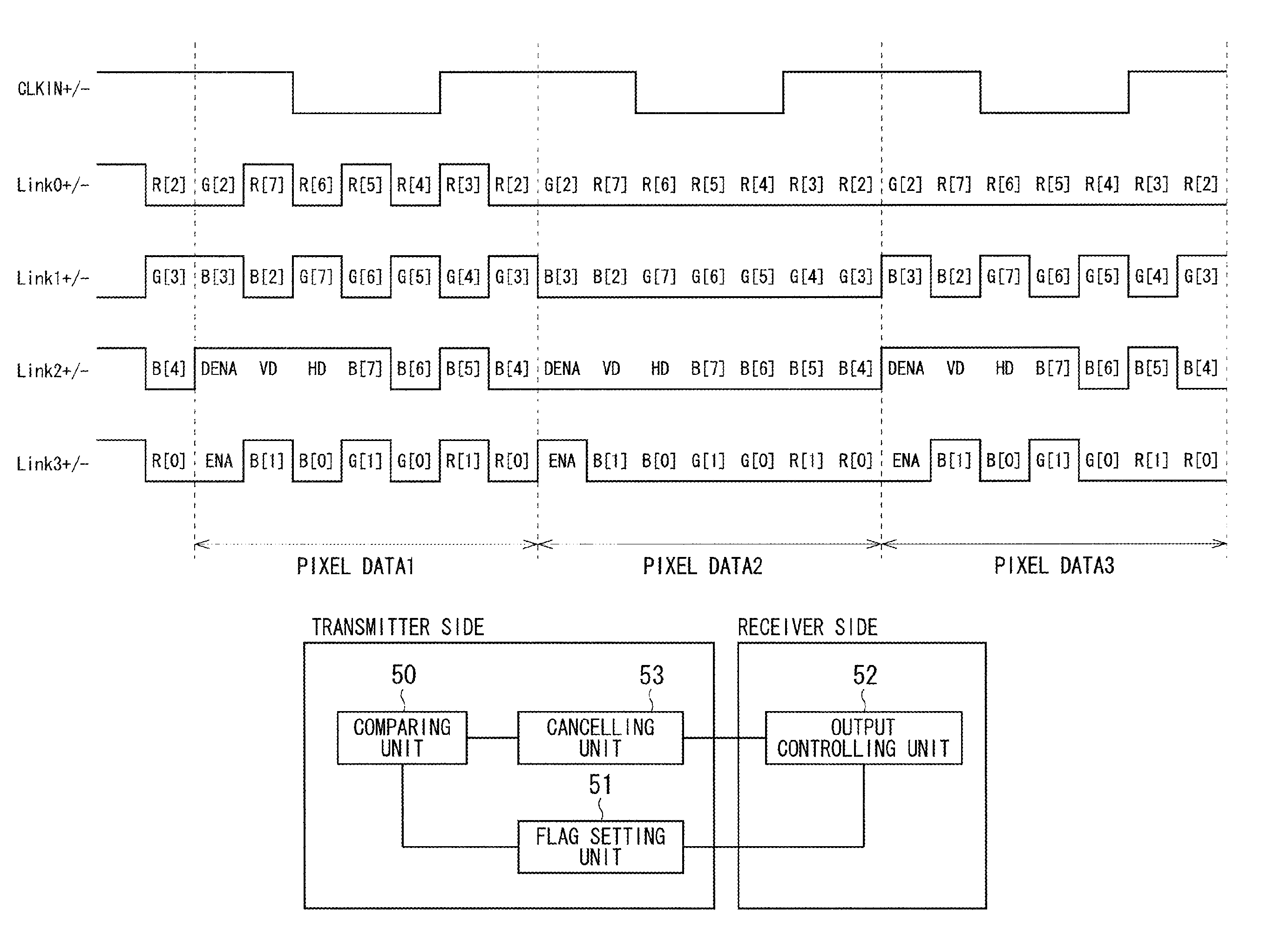
[0044]FIG. 14 is a view illustrating a functional configuration of a data transmission apparatus according to the present invention.

[0045]As illustrated in FIG. 14, the data transmission apparatus has a comparing unit 50, a cancelling unit 53, a flag setting unit 51, and an output controlling unit 52. Among these functional units, the comparing unit 50, the cancelling unit 53, and the flag setting unit 51 are arranged at the transmitter side of the data transmission (corresponding to the scaler chip 15, for example). On the other hand, the output controlling unit 52 is arranged at the receiver side of the data transmission (corresponding to ...

second preferred embodiment

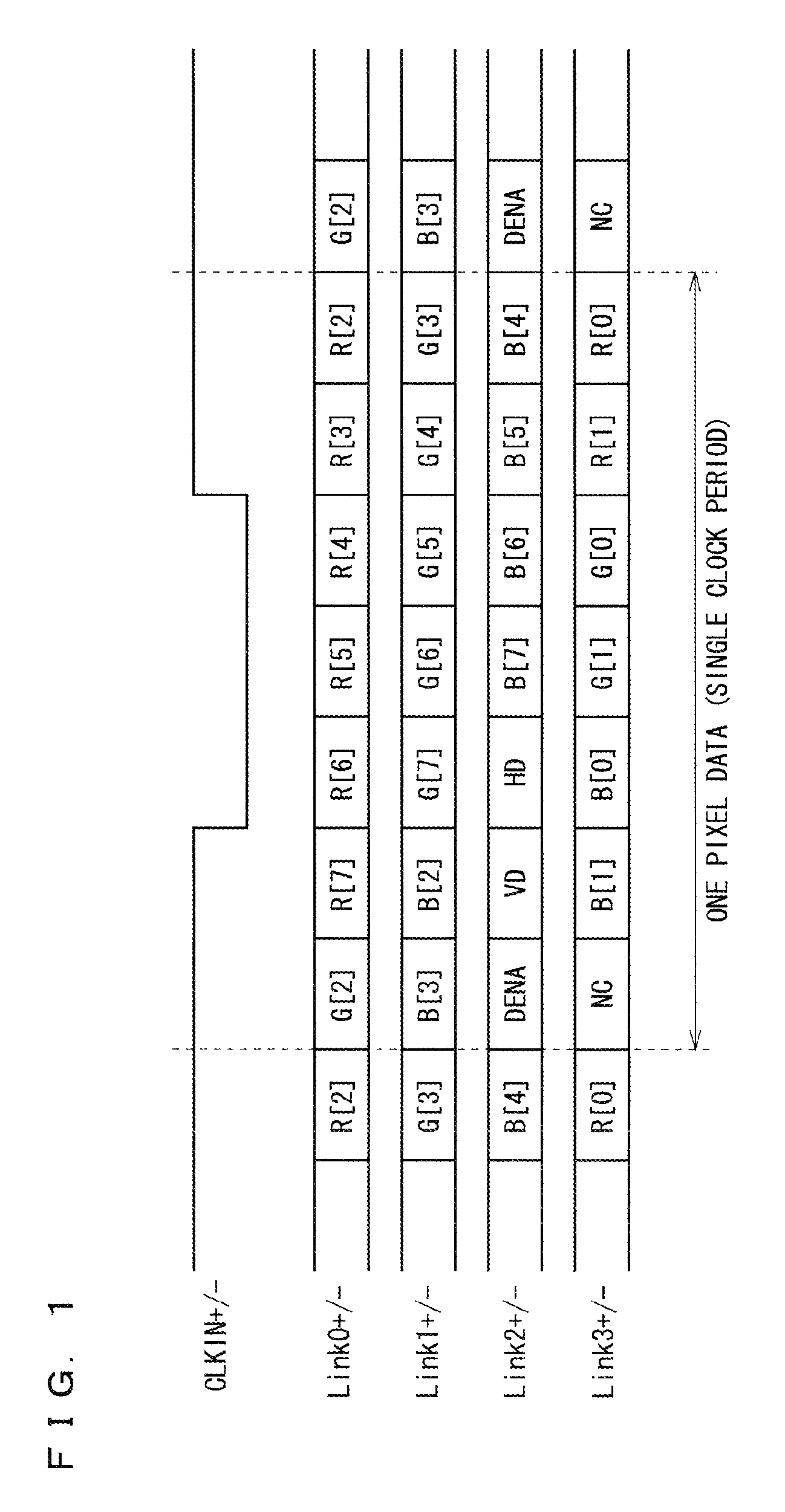
[0092]FIG. 10 is a view illustrating a mapping configuration of 6-bit RGB image signals to be input to a liquid crystal module via a transmission technology of LVDS according to an underlying technique.

[0093]In the case where the mapping has no free space (a time domain which has none of the image signals or the like allocated) as illustrated in FIG. 10, the approach of the first preferred embodiment is not available. Then, in the second preferred embodiment, a particular combination of a plurality of control signals allocated in a clock period is used.

[0094]Assuming that the control signals (DENA, HD, VD) are defined as in the first preferred embodiment, the periods in which HD and VD are in the High state need to synchronize with the period in which DENA is in the High state. Conversely, the periods in which HD and VD are in the Low state synchronized with the period in which DENA is in the High state are impossible combinations of the control signals. In other words, these combin...


PUM


Abstract

The present invention has a comparing unit that compares each of image signals in a first clock period with a corresponding one of the image signals in a second clock period subsequent to the first clock period, and a cancelling unit that causes each of the image signals in the second clock period to be cancelled in the case where a comparison result from the comparing unit indicates that each of the image signals in the first clock period agrees with the corresponding one of the image signals in the second clock period.

Description

BACKGROUND OF THE INVENTION[0001]1. Field of the Invention[0002]The present invention relates to a data transmission apparatus and a data transmission method and particularly to a data transmission apparatus and a data transmission method for serially transmitting a plurality of image signals to an image display device by using digital data which has the image signals allocated in a single clock period.[0003]2. Description of the Background Art[0004]For the purpose of power saving and reduction of the number of transmission links, data transmission apparatuses adopting such technologies as LVDS (Low voltage differential signaling) which serially transmits a plurality of image signals by allocating (mapping) the image signals in a single clock period have been widely used (for example, Japanese Patent Application Laid-Open Nos. 2008-287154 and 2010-210693). That transmission method identifies each of the plurality of allocated image signals by detecting a voltage difference between p...

Claims


Application Information

Patent Timeline
Patent Type & Authority Patents(United States)
IPC IPC(8): G09G3/20G09G3/36
CPCG09G3/2096G09G3/3611G09G2330/06G09G2370/14
Inventor MINAMI, AKIHIRO
Owner MITSUBISHI ELECTRIC CORP
Why Eureka
Try Eureka