Non-invasive method for resonant frequency detection in corona ignition systems

Active Publication Date: 2015-06-18
FEDERAL MOGUL MOTORPARTS LLC
View PDF4 Cites 12 Cited by
  • Summary
  • Abstract
  • Description
  • Claims
  • Application Information

AI Technical Summary

Benefits of technology

[0009]By measuring the resonant frequency of the corona igniter during the idle second period of time, when no energy is being provided to the corona igniter, an accurate measurement of the true resonant frequency of the corona igniter is obtained. During this idle period, the resonant frequency measured is dependent only on the corona igniter, and not any other components of the system. This accurate resonant frequency measurement can then be supplied to the corona igniter dur

Problems solved by technology

However, accurate detection of the resonant frequency it is difficult to achieve, especially at a wide range of frequencies.
Changes in the

Method used


Image

  • Non-invasive method for resonant frequency detection in corona ignition systems
  • Non-invasive method for resonant frequency detection in corona ignition systems
  • Non-invasive method for resonant frequency detection in corona ignition systems

Examples


Embodiment Construction

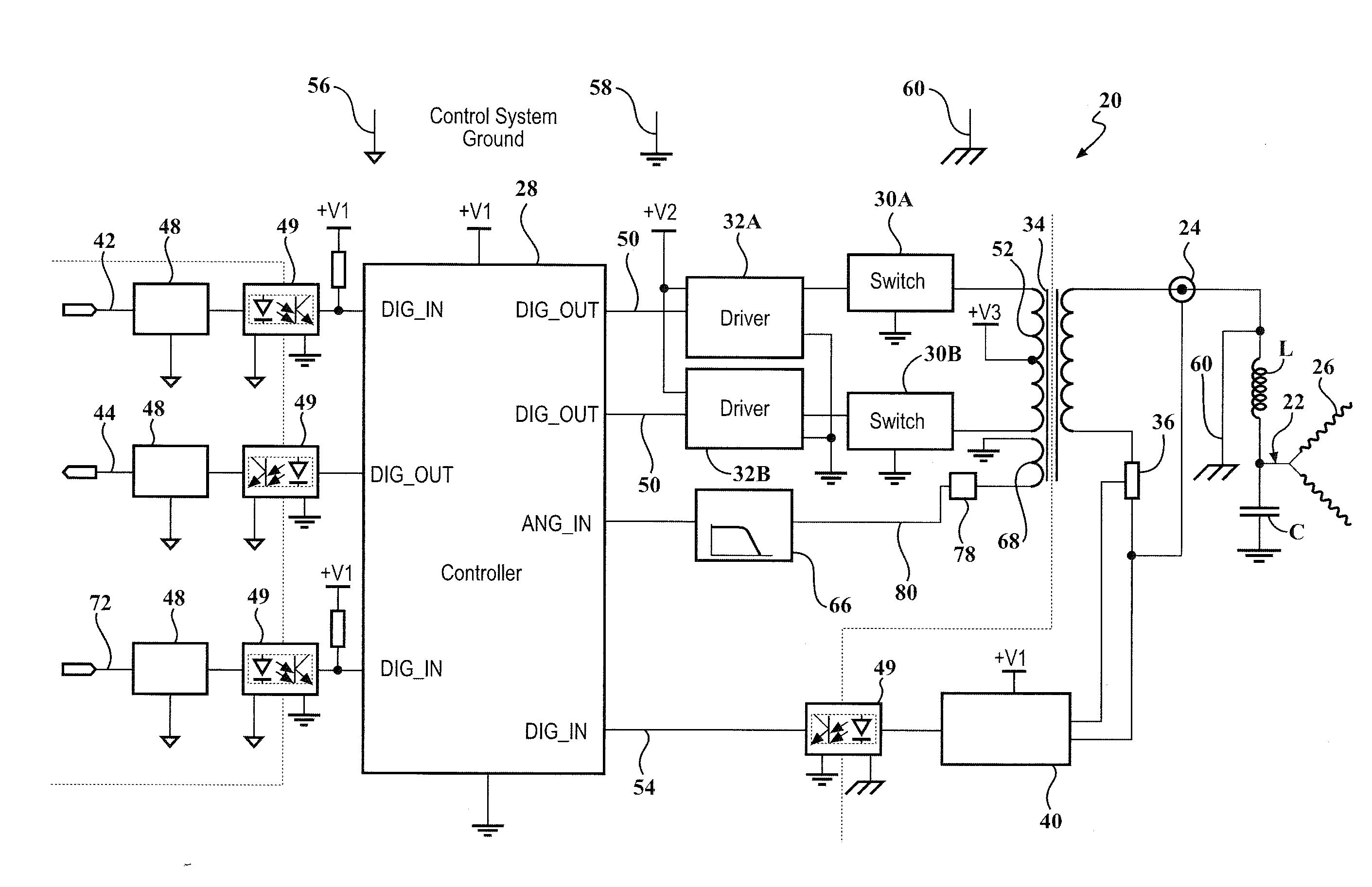
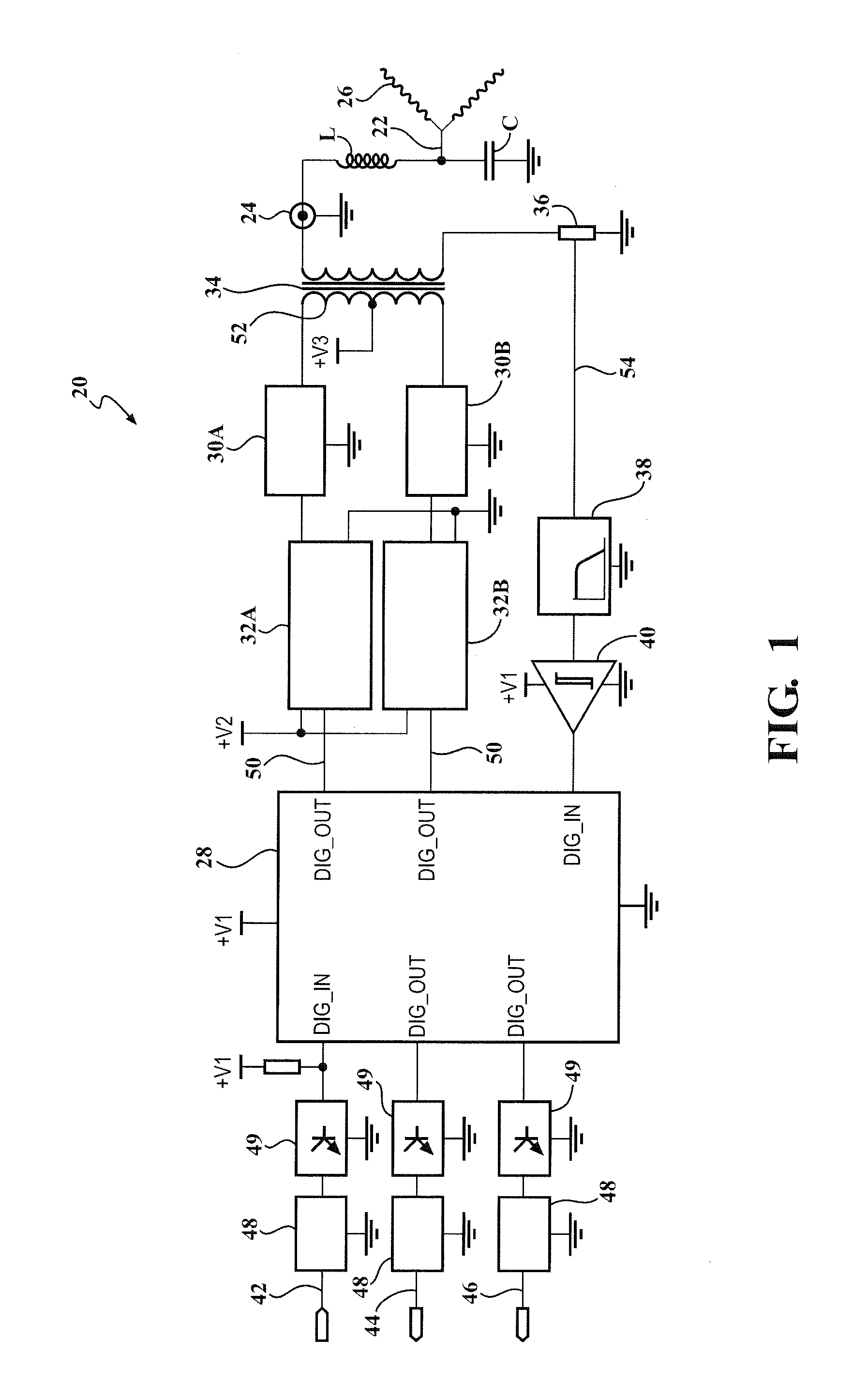
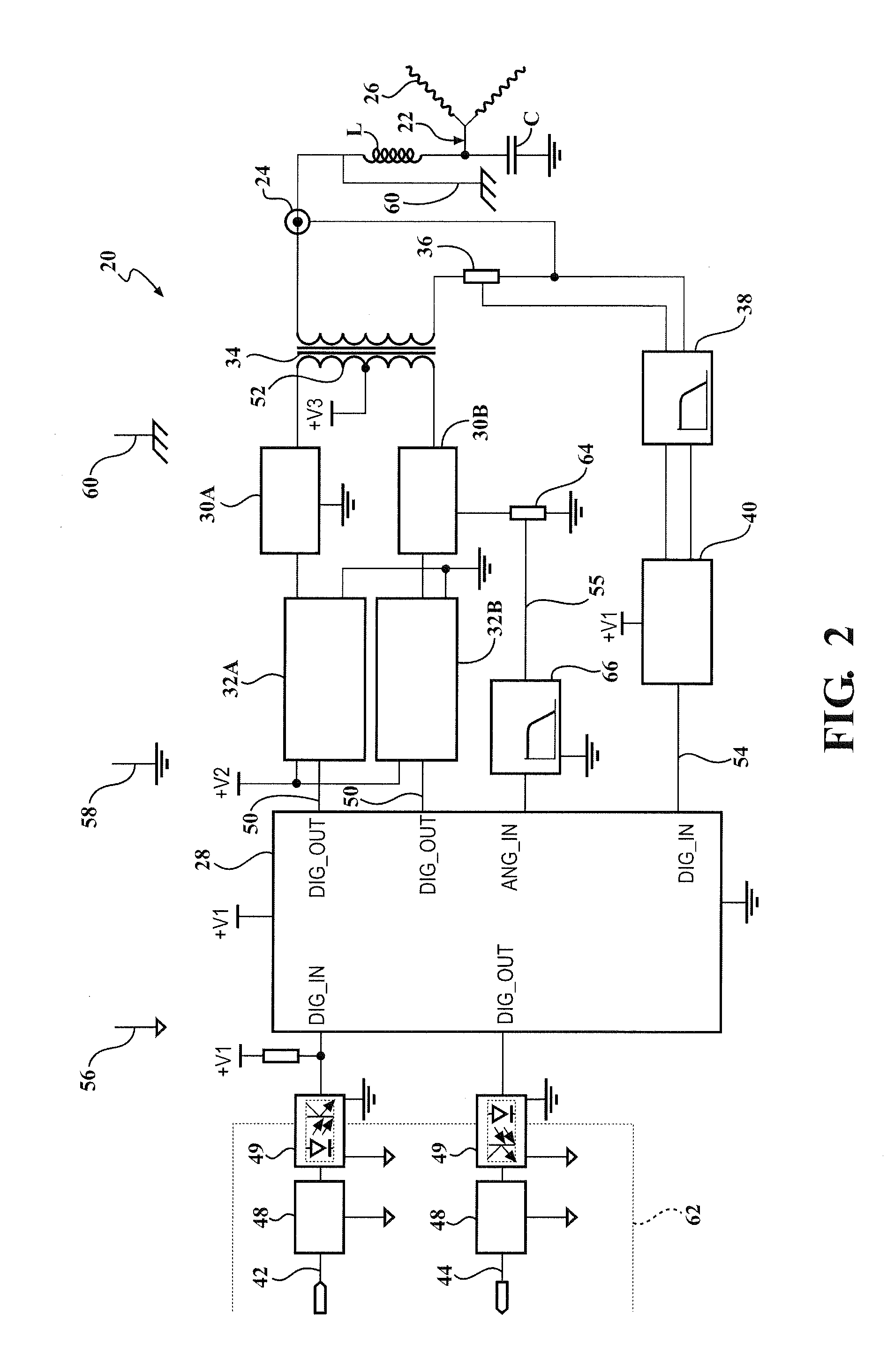
[0016]The present invention provides a corona discharge ignition system 20 and method providing improved resonant frequency detection. The system 20 comprises a corona igniter 22 including an induction coil L and capacitor C, together referred to as the load, which operate at a resonant frequency. The corona igniter 22 receives energy at a drive frequency and provides a current and voltage at an input 24. An energy supply V3 provides the energy to the corona igniter 22 at a first drive frequency during a first period of time 101, referred to as a corona event, and during which the corona igniter 22 provides corona discharge 26 in a combustion chamber. The energy supply to the corona igniter 22 is ceased for a second period of time 102, referred to as an idle period, and provided again during a third period of time 103, referred to as another corona event. Some of the energy provided during the first period of time 101 is stored in the corona igniter 22 during the idle second period ...


PUM


Abstract

A corona ignition system including a corona igniter, an energy supply, and a frequency detector is provided. The energy supply provides energy to the corona igniter during corona events which are spaced from one another by idle periods, during which no energy is provided to the corona igniter. During the idle periods, the frequency detector obtains the resonant frequency of the corona igniter from at least one of an output voltage and an output current of the energy stored in the corona igniter. The resonant frequency measured during this idle period is dependent only on the corona igniter, and not any other components of the system, and thus is very accurate. The drive frequency of future corona events can then be set based on this accurately measured resonant frequency to achieve a robust corona discharge.

Description

CROSS-REFERENCE TO RELATED APPLICATIONS[0001]This U.S. patent application claims the benefit of U.S. provisional patent application No. 61 / 915,088 (Attorney Docket No. 710240-6793; IA-50129), filed Dec. 12, 2013; U.S. provisional patent application No. 61 / 931,131 (Attorney Docket No. 710240-6830; IA-50134), filed Jan. 24, 2014; U.S. provisional patent application No. 61 / 950,991 (Attorney Docket No. 712040-6901; IA-50147), filed Mar. 11, 2014; U.S. provisional patent application No. 62 / 072,530 (Attorney Docket No. 710240-7346; IA-51029-1), filed Oct. 30, 2014; and U.S. provisional patent application No. 62 / 090,096 (Attorney Docket No. 710240-7356; IA-50359), filed Dec. 10, 2014, the entire contents of each being incorporated herein by reference in their entirety.BACKGROUND OF THE INVENTION[0002]1. Field of the Invention[0003]This invention relates generally to a corona discharge ignition system, and more particularly to controlling energy supplied to the system.[0004]2. Related Art[0...

Claims


Application Information

Patent Timeline
IPC IPC(8): H01T19/00
CPCH01T19/00F02P3/0407F02P5/1502F02P17/00F02N2300/2011F02P23/04Y02T10/40G01M15/02G01N27/02H01T15/00
Inventor BURROWS, JOHN ANTONY
Owner FEDERAL MOGUL MOTORPARTS LLC
Why Eureka
Try Eureka