Two Phase Gap Cooling of an Electrical Machine

a technology of electrical machines and gap cooling, which is applied in the direction of cooling/ventilation arrangements, electrical apparatus, dynamo-electric machines, etc., can solve the problems of excessive heat transfer, excessive heat loss, and ineffective cooling, so as to reduce friction and windage loss, reduce heat loss, and reduce heat loss

Active Publication Date: 2015-06-18
BALDOR ELECTRIC COMPANY
View PDF5 Cites 15 Cited by
  • Summary
  • Abstract
  • Description
  • Claims
  • Application Information

AI Technical Summary

Benefits of technology

[0003]These disadvantages may be overcome. Substantial cooling of electrical machines may be achieved by directing a mixture of gas and cooling liquid or coolant, (for instance, oil and air) through the gap between the rotor and stator of the electro-dynamic machine. The amount of coolant is controlled to maintain friction and windage losses at an acceptable level. The gas may be pressurized to generate the flow of the gas and coolant mixture through the gap. As will be further discussed in great detail below, the methods and constructions of the electro-dynamic machine enable the gas—coolant mixture to be directed to the gap between a rotor and stator, thereby putting the rotor in close contact with the gas-coolant mixture for enhanced cooling of the electrical machine.

Problems solved by technology

In synchronous reluctance permanent magnet motors, interior permanent magnet motors, and surface permanent magnet motors, the rotor often becomes the hottest part of the motor during operation as it is the most difficult to effectively cool.
The excessive temperature tends to degrade magnet performance and motor efficiency.
Often in these types of motors, excessive heat is transferred from the rotor to the stator through the gap between the rotor and the stator.
While liquid coolants, such as oil, may be used in the interior of the motor to cool the internal motor components, traditional methods of cooling with liquid coolants typically result in prohibitively high friction and windage losses.
Filling the internal volume of the motor with oil, typically creates high friction and windage losses.

Method used


Image

  • Two Phase Gap Cooling of an Electrical Machine
  • Two Phase Gap Cooling of an Electrical Machine
  • Two Phase Gap Cooling of an Electrical Machine

Examples


Embodiment Construction

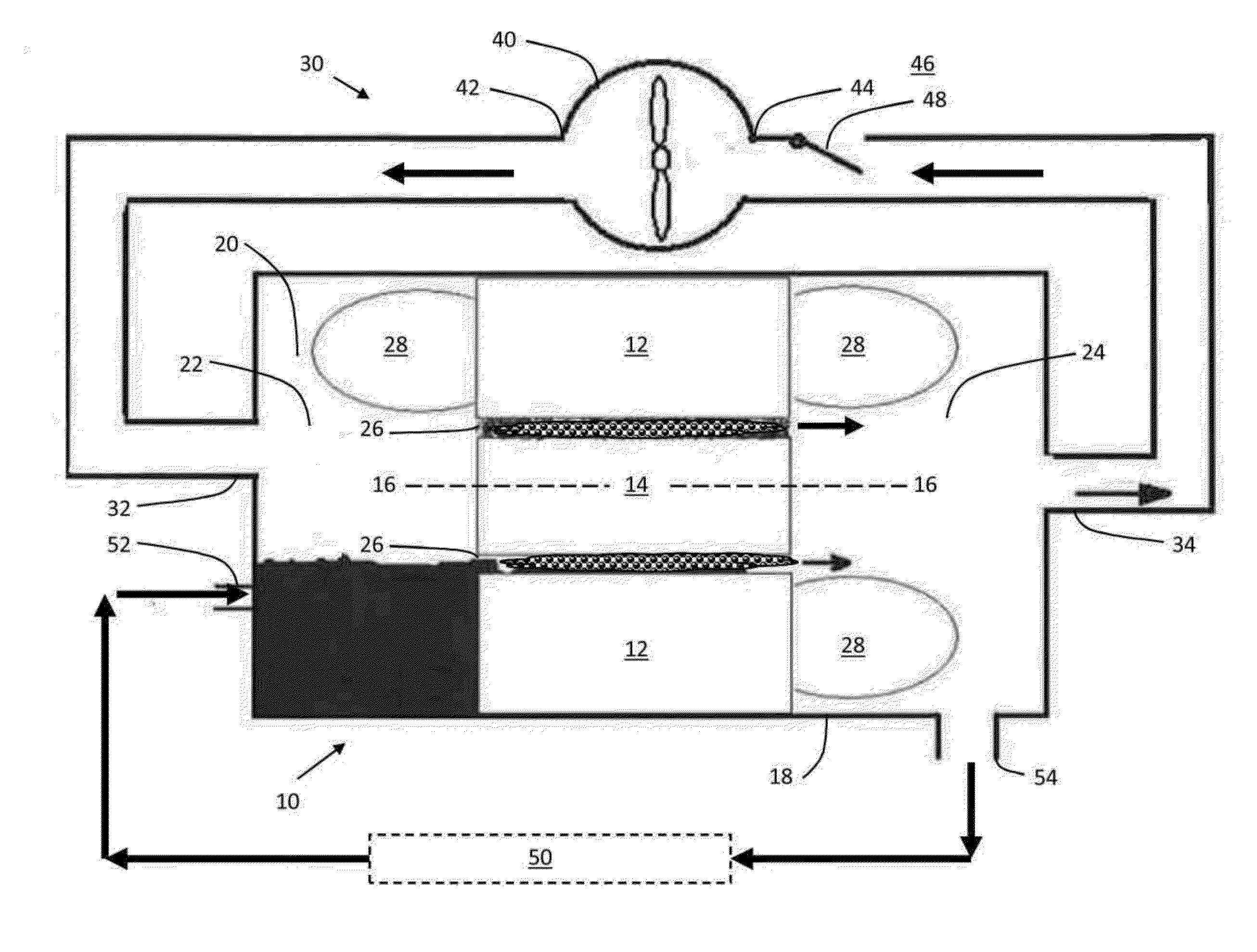
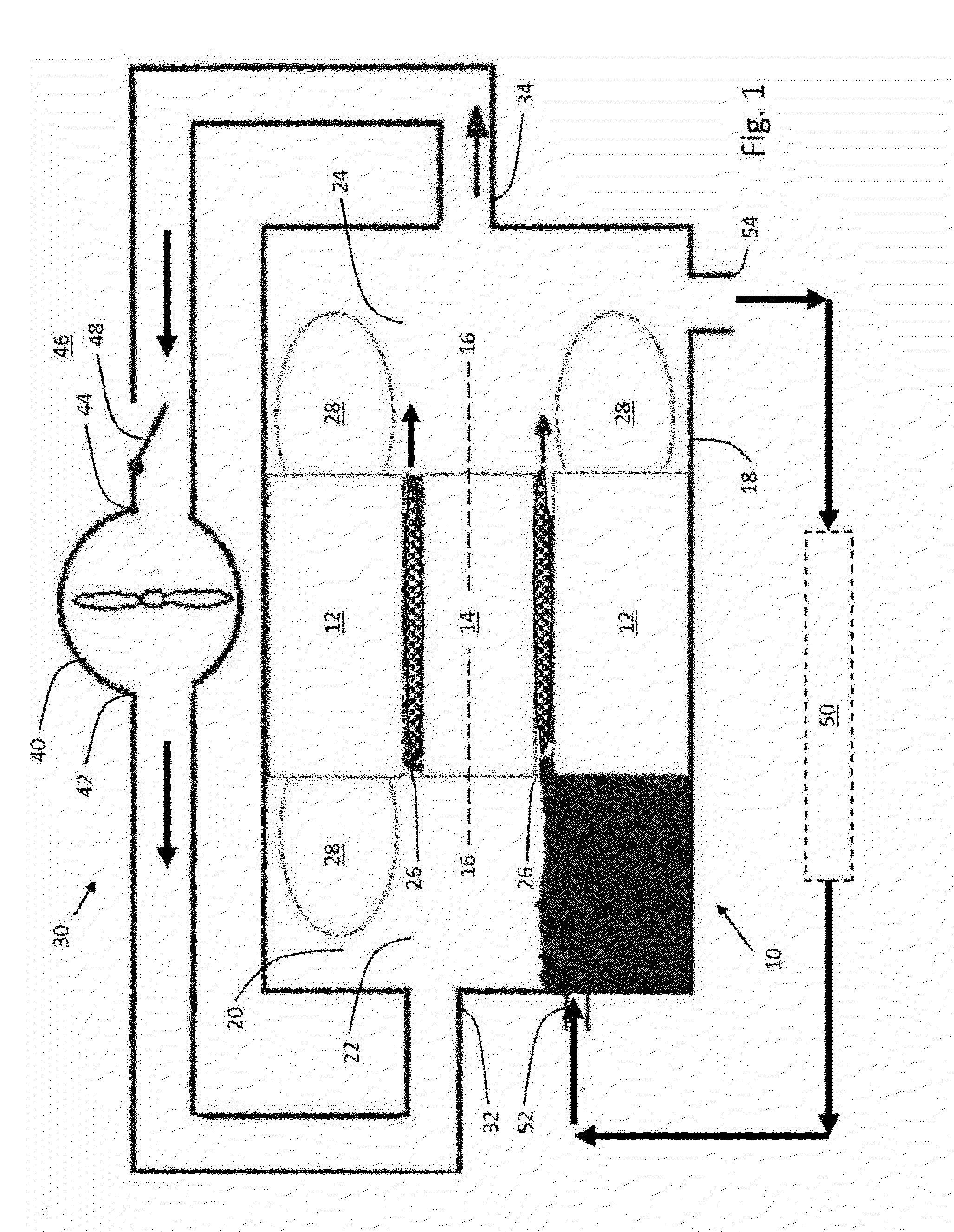
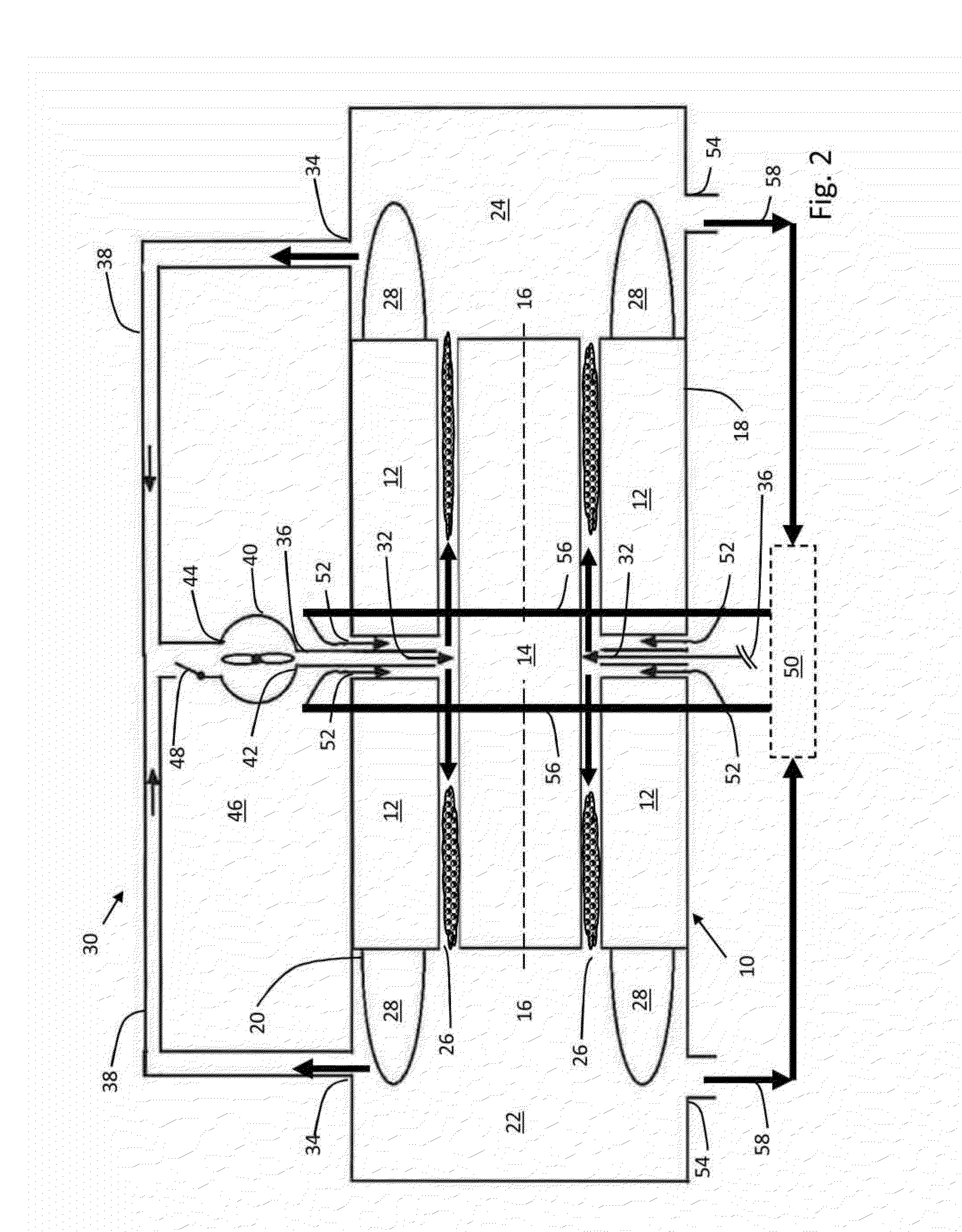
[0008]Although the embodiments described below are in the context of an electrical motor, the principles disclosed herein may be used with any electro-dynamic machine, such as a generator or other rotating electrical machine, and not intended to be limiting in any sense. Also, although the term “oil” is used in the description, the use is not intended to limit the embodiments in any sense, and any suitable liquid coolants may be used instead of oil, including by way of example, oil based coolants, water based coolants, synthetic fluids, etc. Also, although the term “gas” is used in the description, the use is not intended to limit the embodiments in any sense, and any suitable gas may be used, including air. Also, the terms “top”, “bottom”, “left,” and right” are used in the description that follows for ease of describing features illustrated in the drawings, and their use is not intended to limit any of the embodiments so described.

[0009]The motor 10 comprises a stator 12 and a rot...


PUM


Abstract

An electro-dynamic machine has a rotor and stator with a gap therebetween. The machine has a frame defining a hollow interior with end cavities on axially opposite ends of the frame. A gas circulating system has an inlet that supplies high pressure gas to the frame interior and an outlet to collect gas passing therethrough. A liquid coolant circulating system has an inlet that supplies coolant to the frame interior and an outlet that collects coolant passing therethrough. The coolant inlet and gas inlet are generally located on the frame in a manner to allow coolant from the coolant inlet to flow with gas from the gas inlet to the gap. The coolant outlet and gas outlet are generally located on the frame in a manner to allow the coolant to be separated from the gas with the separated coolant and gas collected for circulation through their respective circulating systems.

Description

STATEMENT REGARDING FEDERALLY SPONSORED RESEARCH OR DEVELOPMENT[0001]This invention was made with government support under agreement No. DE-AR0000191 awarded by the Department of Energy. The government has certain rights in this invention.BACKGROUND AND SUMMARY[0002]In synchronous reluctance permanent magnet motors, interior permanent magnet motors, and surface permanent magnet motors, the rotor often becomes the hottest part of the motor during operation as it is the most difficult to effectively cool. The excessive temperature tends to degrade magnet performance and motor efficiency. Often in these types of motors, excessive heat is transferred from the rotor to the stator through the gap between the rotor and the stator. Thus, in addition to an increase of rotor temperature, stator temperature also increases. While liquid coolants, such as oil, may be used in the interior of the motor to cool the internal motor components, traditional methods of cooling with liquid coolants typic...

Claims


Application Information

Patent Timeline
Patent Type & Authority Applications(United States)
IPC IPC(8): H02K9/00
CPCH02K9/005H02K9/12H02K9/19H02K9/00
Inventor SHOYKHET, BORIS A.
Owner BALDOR ELECTRIC COMPANY
Why Eureka
Try Eureka