Method and Apparatus for Preventing Digital Step Attenuator Output Power Peaking During Attenuation State Transitions

a digital step attenuator and output power technology, applied in electrical apparatus, multiple-port network, frequency-dependent attenuators, etc., can solve problems such as unwanted detection errors, component switching elements in attenuator stages that do not turn, and glitches that can degrade the performance of or damage a system in which such a dsa is embedded, so as to reduce positive switching transients (glitches), reduce power, and increase attenuation

Active Publication Date: 2015-06-18
PSEMI CORP
View PDF2 Cites 25 Cited by
  • Summary
  • Abstract
  • Description
  • Claims
  • Application Information

AI Technical Summary

Benefits of technology

[0013]The invention is a method and circuit for significantly reducing positive switching transients (glitches) of digital step attenuators (DSA's) by controlling the timing of state transitions for individual attenuator stages within a DSA. Such control prevents the DSA output power from peaking during attenuation state transitions and ensures that any transient glitch during the transition results in reduced power at the DSA output. Attenuation stage timing delay can be implemented on an integrated circuit die or “chip” for monolithic implementations of a DSA by adding circuitry which ensures that any attenuation state changes result in increased attenuation rather than decreased attenuation, thereby reducing or eliminating positive transient glitches at the DSA output.
[0014]An aspect of the invention is to begin switching selected attenuator stages going from the OFF state (insertion loss mode) to the ON state (attenuation mode) first during attenuation state changes, and concurrently delaying the onset of attenuator stages going from the ON state (attenuation mode) to the OFF state (insertion loss mode) by a sufficient amount of time to ensure that any glitch present at the output would be in the direction of reduced output power to eliminate positive output glitches. This is accomplished by adding an attenuation state dependent delay element to the control timing of at least each most significant-bit individual attenuator stage in the DSA.

Problems solved by technology

A problem with a conventional binary-weighted DSA 100 is that the component switching elements in the attenuator stages do not turn ON and OFF at the same rate.
While the peak in output power lasts for only a short duration (tens of nanoseconds to a couple hundred nanoseconds) during an attenuation state change, if the power level is too great, the transient glitch can degrade the performance of or damage a system in which such a DSA is embedded.
When such a DSA is part of an automatic gain control loop (AGC) used to compensate for variations in received signal strength, such glitches may introduce an unwanted detection error.
For other types of load devices or circuits, the peak power during a transition glitch may be damaging.

Method used


Image

  • Method and Apparatus for Preventing Digital Step Attenuator Output Power Peaking During Attenuation State Transitions
  • Method and Apparatus for Preventing Digital Step Attenuator Output Power Peaking During Attenuation State Transitions
  • Method and Apparatus for Preventing Digital Step Attenuator Output Power Peaking During Attenuation State Transitions

Examples


Embodiment Construction

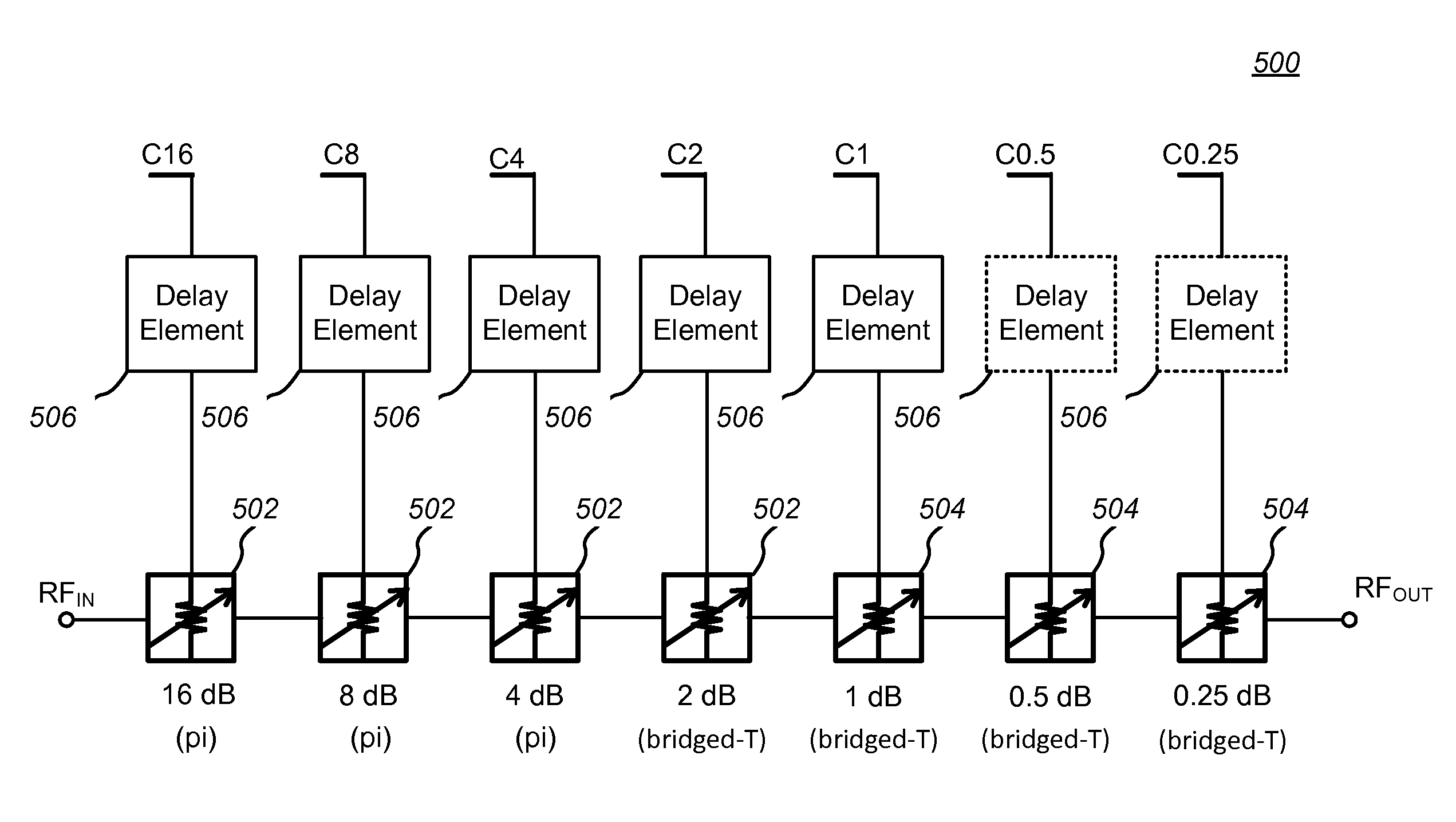
[0024]The invention is a method and circuit for significantly reducing positive switching transients (glitches) of digital step attenuators (DSA's) by controlling the timing of state transitions for individual attenuator stages within a DSA. Such control prevents the DSA output power from peaking during attenuation state transitions and ensures that any transient glitch during the transition results in reduced power at the DSA output. Attenuation stage timing delay can be implemented on an integrated circuit die or “chip” for monolithic implementations of a DSA by adding circuitry which ensures that any attenuation state changes result in increased attenuation rather than decreased attenuation, thereby reducing or eliminating positive transient glitches at the DSA output.

[0025]An aspect of the invention is to begin switching selected attenuator stages going from the OFF state (insertion loss mode) to the ON state (attenuation mode) first during attenuation state changes, and delayin...


PUM


Abstract

A method and circuit for significantly reducing positive switching transients (glitches) of digital step attenuators (DSA's) by controlling the timing of state transitions for individual attenuator stages within a DSA. Such control prevents the DSA output power from peaking during attenuation state transitions and ensures that any transient glitch during the transition results in reduced power at the DSA output. Attenuation stage timing delay can be implemented on an integrated circuit die or “chip” for monolithic implementations of a DSA by adding circuitry which ensures that any attenuation state changes result in increased attenuation rather than decreased attenuation, thereby reducing or eliminating positive transient glitches at the DSA output.

Description

BACKGROUND[0001](1) Technical Field[0002]This invention generally relates to electronic circuits, and more specifically to digital step attenuator circuits.[0003](2) Background[0004]An attenuator is an electronic device that reduces the power of a signal without appreciably distorting its waveform. Attenuators are usually passive devices made from simple voltage divider networks, and are frequently used to lower voltage, dissipate power, and / or to improve impedance matching. For example, in measuring signals, attenuators are used to lower the amplitude of a signal under test a known amount to enable measurements, or to protect the measuring device from signal levels that might damage it. Attenuators are also used to match impedance by lowering the apparent standing wave ratio (SWR).[0005]Digital step attenuators (DSA's) are frequently used with radio frequency (RF) systems such as transceivers for broadcast radio, cellular telephones, and RF based digital networks (e.g., WiFi, Bluet...

Claims


Application Information

Patent Timeline
Patent Type & Authority Applications(United States)
IPC IPC(8): H03H11/24H01P1/22
CPCH03H11/245
Inventor LAM, FLEMING
Owner PSEMI CORP
Why Eureka
Try Eureka