Lighting device and luminaire

a technology of light-emitting devices and luminaires, which is applied in the direction of lighting devices, electrical devices, light sources, etc., can solve the problems of excessive current flowing in the other normal, deteriorating or failing normal leds, and affecting the normal operation of normal light-emitting elements, so as to prevent the normal light-emitting elements from deteriorating or failing, and suppress excessive current.

Inactive Publication Date: 2015-06-18
PANASONIC INTELLECTUAL PROPERTY MANAGEMENT CO LTD
View PDF6 Cites 27 Cited by
  • Summary
  • Abstract
  • Description
  • Claims
  • Application Information

AI Technical Summary

Benefits of technology

[0019]In view of the above, the present invention provides a lighting device, with solid-state light-emitting elements connected in series and bypass circuits, capable of suppressing excessive current from flowing in normal light-emitting elements at the moment when a bypass circuit is turned on.
[0023]Further, during the discharge period, the bypass control unit may stop the constant-current circuit or may reduce a value of the constant current supplied from the constant-current circuit.
[0037]In accordance with the aspects of the present invention, in a lighting device with solid-state light-emitting elements connected in series and bypass circuits, the lighting device can suppress excessive current from flowing in normal light-emitting elements at the moment when a bypass circuit is turned on.
[0038]Accordingly, it is possible to prevent the normal light-emitting elements from deteriorating or failing.

Problems solved by technology

For such a luminaire, however, excessive current may flow in the other normal LEDs when the bypass circuit is operated.
As a result, the normal LEDs may deteriorate or fail.
In this instance, however, immediately after the bypass switch is turned on, excessive current flows in the other LEDs having no open-circuit failure and in the corresponding bypass circuit.
Therefore, in the above disclosure, normal LEDs may deteriorate or fail.
In order to prevent the LEDs from deteriorating or failing, the LEDs or the like need to be robust to stress due to such excessive current, causing the cost and size to be increased.
However, this approach may cause another problem in that the bypass circuit 104b has more power loss.
In this approach, however, the power loss is continuously generated by the voltage drop unit after connecting two ends of the LED having the open-circuit failure.

Method used


Image

  • Lighting device and luminaire
  • Lighting device and luminaire
  • Lighting device and luminaire

Examples


first embodiment

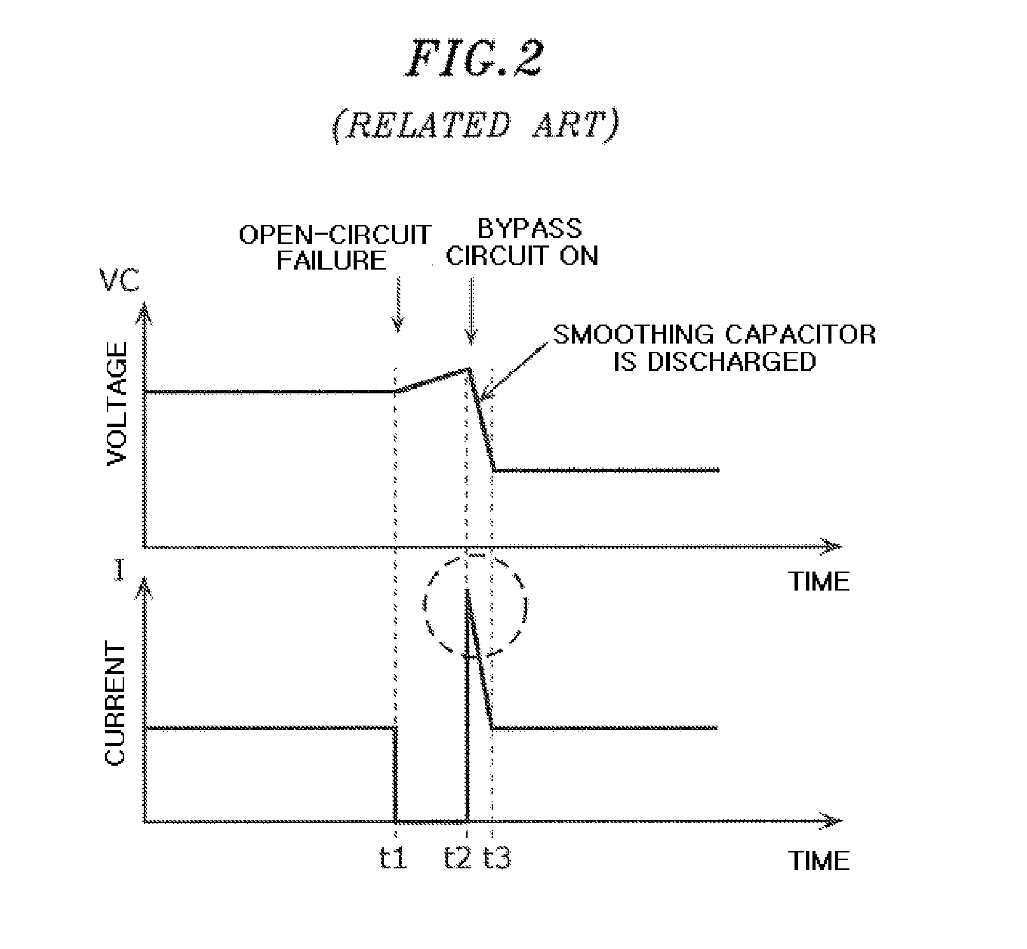
[0081]According to the first embodiment, when an open-circuit failure has occurred, a luminaire releases electric charges accumulated in a smoothing capacitor and then turns on a bypass circuit. Specifically, the luminaire releases electric charges accumulated in the smoothing capacitor by interrupting a constant-current circuit for a predetermined time period after the open-circuit failure has occurred. By doing so, it is possible to suppress excessive current flowing in normal light-emitting elements when the bypass circuit is turned on.

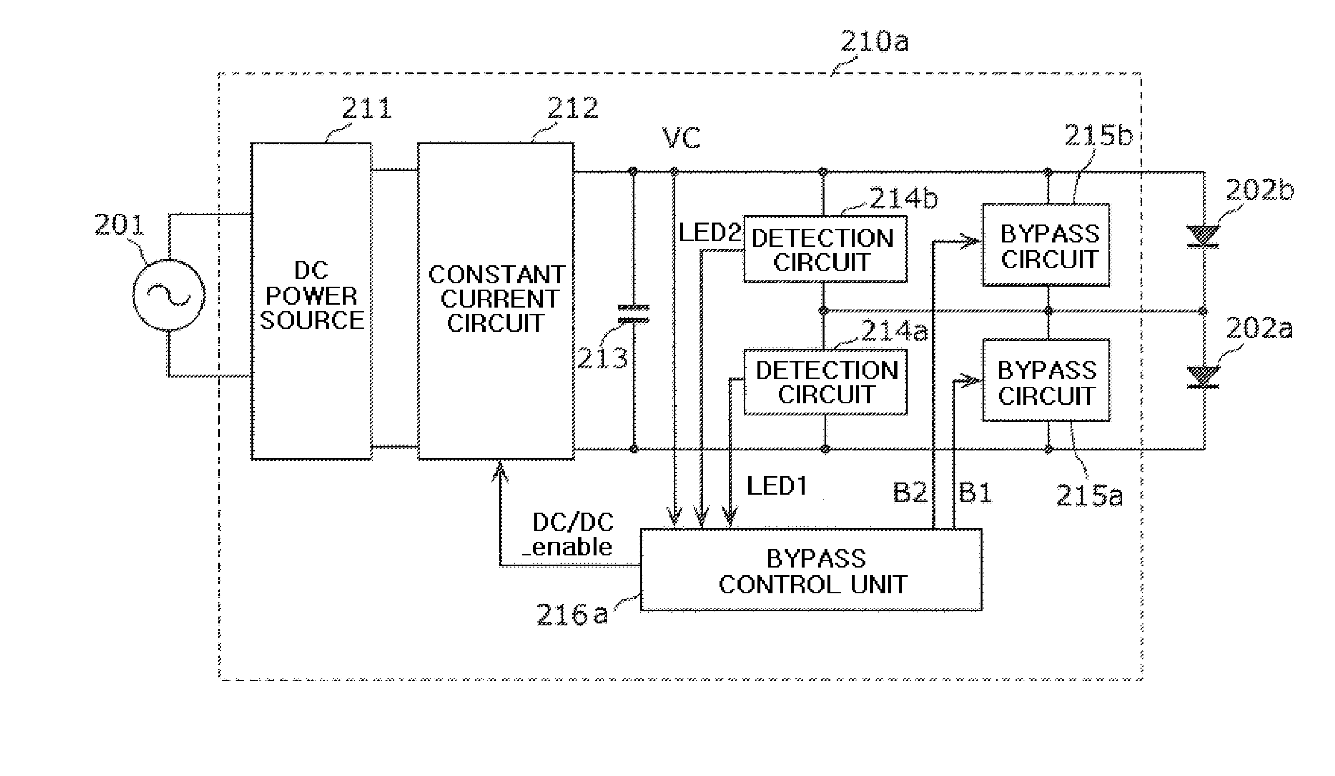
[0082]FIG. 3 is a circuit diagram of a lighting device 210a according to the first embodiment of the present invention.

[0083]The lighting device 210a lights solid-state light-emitting elements connected in series to each other, e.g., LEDs 202a and 202b, by using power from a commercial power source 201. The lighting device 210a includes a DC power source 211, a constant-current circuit 212, a smoothing capacitor 213, a detection circuits 214a and 2...

second embodiment

[0126]The second embodiment to be described below is a modification of the first embodiment. In addition to the elements of the first embodiment, the lighting device 210b according to the second embodiment further includes a discharge circuit for discharging electric charges in the smoothing capacitor 213 during the discharge period.

[0127]In the following description, descriptions will be made focusing on differences between the first and second embodiments, and redundant descriptions on the same elements will be omitted.

[0128]FIG. 7 is a circuit diagram of a lighting device 210b according to the second embodiment of the present invention. In addition to the elements shown in FIG. 3, the lighting device 210b shown in FIG. 7 further includes a discharge circuit 220. The bypass control unit 216b includes the functionality of the bypass control unit 216a.

[0129]The discharge circuit 220 is connected in parallel to the smoothing capacitor 213 and includes a switching element connected i...

third embodiment

[0138]In the above embodiments, the discharge period terminates when the voltage VC becomes lower than the predetermined voltage Vf_min. According to the third embodiment, the discharge period terminates after a predetermined time period has elapsed from the start of the discharge period.

[0139]FIG. 12 is a circuit diagram of a lighting device 210d according to the third embodiment of the present invention. The configuration of the lighting device 210d shown in FIG. 12 is identical to that of FIG. 7 except that the configuration of a bypass control unit 216d is different from that of the bypass control unit 216b. As in the configuration shown in FIG. 7, the configuration in which the discharge circuit 220 is employed and the constant-current circuit 212 stops during the discharge period will be described as an example in this embodiment. However, the discharge circuit 220 may not be employed or the constant-current circuit 212 may not stop during the discharge period.

[0140]The bypass...


PUM


Abstract

A lighting device includes a constant-current circuit, a smoothing capacitor, a bypass circuit, a detection unit, and a bypass control unit. The constant-current circuit supplies a constant current to a plurality of solid-state light-emitting elements connected in series. The smoothing capacitor is connected between output terminals of the constant-current circuit. The bypass circuit is connected in parallel to one or more of the plurality of solid-state light-emitting elements. The detection unit detects whether the one or more solid-state light-emitting elements are open-circuited. When the detection unit detects that at least one of the one or more solid-state light-emitting elements is open-circuited, the bypass control unit discharges the smoothing capacitor during a discharge period to then bypass the one or more solid-state light-emitting elements through the bypass circuit.

Description

CROSS-REFERENCE TO RELATED APPLICATION [0001]This application claims the benefit of priorities of Japanese Patent Application Nos. 2013-261624, filed on Dec. 18, 2013 and 2013-262717, filed on Dec. 19, 2013, the entire contents of which are hereby incorporated by reference.TECHNICAL FIELD[0002]The present invention relates to a lighting device of a solid-state light-emitting element such as an LED (light-emitting diode), and a luminaire having the lighting device.BACKGROUND ART[0003]A solid-state light-emitting element such as an LED is attracting attention as a light source for a variety of products since it is smaller, more efficient, and lasts longer.[0004]Examples of products using LEDs as a light source include a luminaire. The number of LEDs used in a luminaire is determined based on a desired brightness. Typically, a number of LEDs are used for a single luminaire. When a number of LEDs are used in a luminaire, the LEDs may be connected in series to one another. In this arrang...

Claims


Application Information

Patent Timeline
Patent Type & Authority Applications(United States)
IPC IPC(8): H05B33/08H05B44/00
CPCH05B33/08H05B45/48H05B45/54H05B45/375H05B45/3725H05B45/385
Inventor SEKI, KEISUKEKAMOI, TAKESHIYAMAHARA, DAISUKE
Owner PANASONIC INTELLECTUAL PROPERTY MANAGEMENT CO LTD
Why Eureka
Try Eureka