Supercharge Your Innovation With Domain-Expert AI Agents!

Method and system for automatic needle recalibration detection

Inactive Publication Date: 2015-06-25
GENERAL ELECTRIC CO
View PDF4 Cites 15 Cited by
  • Summary
  • Abstract
  • Description
  • Claims
  • Application Information

AI Technical Summary

Benefits of technology

The patent text describes a system and method for automatically detecting when a needle needs to be recalibrated. This helps to prevent errors and ensure accuracy in the needle's measurements. The technical effect of this invention is to improve the reliability and accuracy of needle measurements, which can improve the overall performance and precision of various systems that use the needle.

Problems solved by technology

The smaller the angle at which the needle is inserted relative to the axis of the transducer array, i.e., the imaginary line normal to the face of the transducer array, the more difficult it becomes to visualize the needle.
In a typical biopsy procedure using a linear probe and conventional needle, the geometry is such that most of the transmitted ultrasound energy is reflected by the needle away from the transducer array face and thus is poorly detected by the ultrasound imaging system and may be difficult for the operator to recognize.
However, a subsequent change of magnetic field in the procedure room (e.g., introduction of a metallic object) or even a slight movement (e.g., a rotation) of the hand-held ultrasound probe during a procedure can cause positioning errors in the tracking system, which may necessitate recalibration of the tracking system.
In known tracking systems that use permanent magnets, for example, recalibration is typically performed by removing the surgical instrument that includes the emitter from the surgical environment, which could be inconvenient when the surgical instrument is within a patient, for example.

Method used


Image

  • Method and system for automatic needle recalibration detection
  • Method and system for automatic needle recalibration detection
  • Method and system for automatic needle recalibration detection

Examples


Embodiment Construction

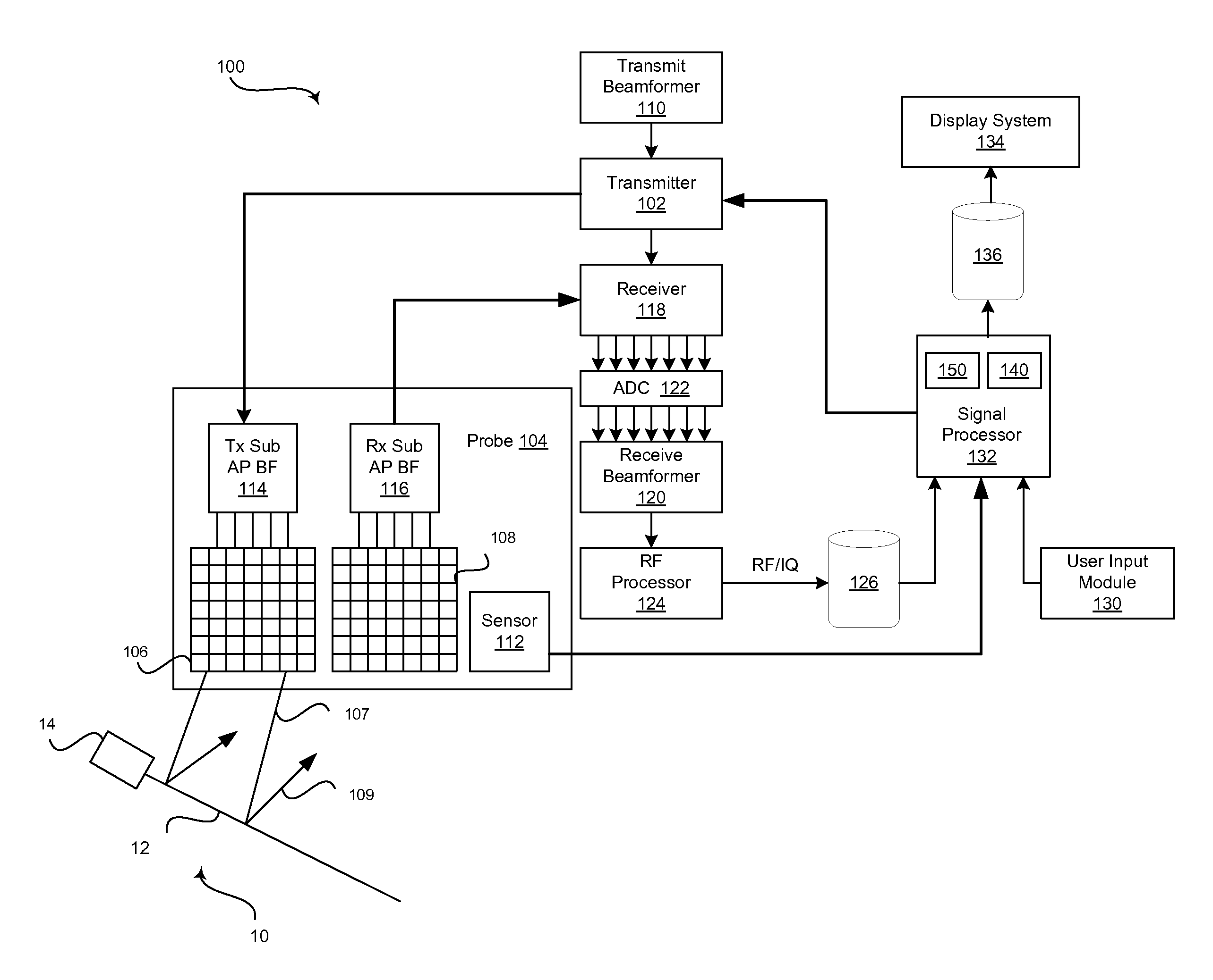
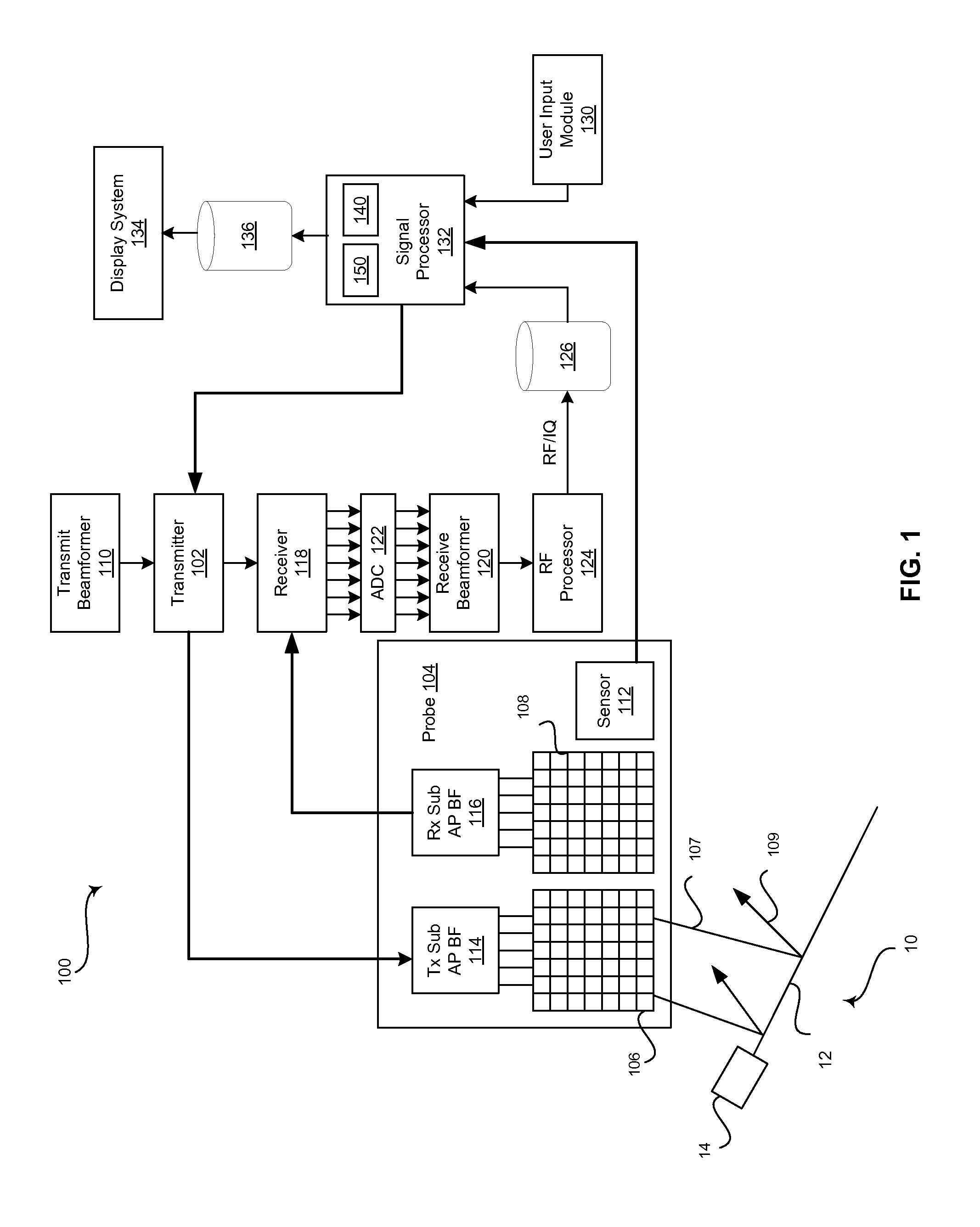
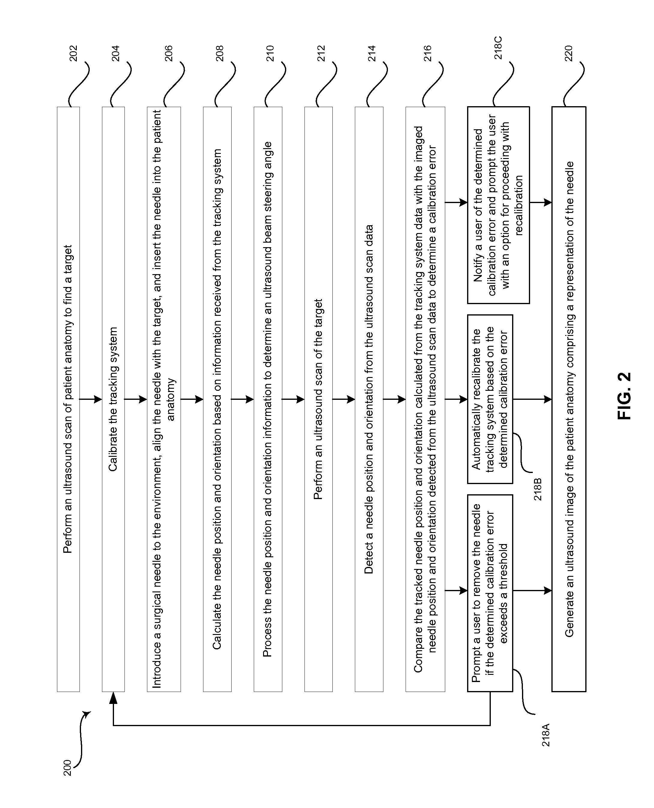
[0015]Certain embodiments of the invention may be found in a method and system for providing automatic needle recalibration detection by comparing a recognized needle position and orientation in ultrasound data with a tracked needle position and orientation provided by a tracking system.

[0016]The foregoing summary, as well as the following detailed description of certain embodiments will be better understood when read in conjunction with the appended drawings. To the extent that the figures illustrate diagrams of the functional blocks of various embodiments, the functional blocks are not necessarily indicative of the division between hardware circuitry. Thus, for example, one or more of the functional blocks (e.g., processors or memories) may be implemented in a single piece of hardware (e.g., a general purpose signal processor or a block of random access memory, hard disk, or the like) or multiple pieces of hardware. Similarly, the programs may be stand alone programs, may be incor...


PUM


Abstract

A tracking system that includes a sensor and emitter is calibrated, and a tracked position and orientation of a surgical instrument is determined based at least in part on tracking information emitted by the emitter and detected by the sensor. An ultrasound system performs an ultrasound scan to acquire ultrasound scan data including the surgical instrument. The ultrasound system determines a scanned position and orientation of the surgical instrument based on the ultrasound scan data. The ultrasound system compares the tracked position and orientation with the scanned position and orientation to determine a calibration error. If the calibration error exceeds a threshold, the ultrasound system may (1) prompt a user to repeat the tracking system calibration step, (2) automatically recalibrate the tracking system and / or the ultrasound system, or (3) provide a user option for proceeding with automatic recalibration of the tracking system and / or the ultrasound system.

Description

CROSS-REFERENCE TO RELATED APPLICATIONS / INCORPORATION BY REFERENCE[0001][Not Applicable]FIELD OF THE INVENTION[0002]Certain embodiments of the invention relate to ultrasound imaging and surgical instrument tracking. More specifically, certain embodiments of the invention relate to a method and system for automatic needle recalibration detection by comparing a recognized needle position and orientation in ultrasound data with a tracked needle position and orientation provided by a tracking system.BACKGROUND OF THE INVENTION[0003]Ultrasound imaging is a medical imaging technique for imaging organs and soft tissues in a human body. Ultrasound imaging uses real time, non-invasive high frequency sound waves to produce a two-dimensional (2D) image and / or a three-dimensional (3D) image.[0004]In conventional ultrasound imaging, an operator of an ultrasound system can acquire images in various modes, such as a non-compounding mode and compounding modes that may include electronically steerin...

Claims


Application Information

Patent Timeline
IPC IPC(8): A61B8/00A61B19/00A61B5/06A61B8/14A61B8/08A61B17/34
CPCA61B8/58A61B8/0841A61B17/3478A61B8/467A61B8/461A61B2019/5276A61B8/14A61B19/54A61B19/5225A61B2019/5458A61B5/062A61B8/585A61B90/37A61B2090/378A61B90/39A61B2090/3958
Inventor BATES, DAVID J.HALMANN, MENACHEM
Owner GENERAL ELECTRIC CO
Features
  • R&D
  • Intellectual Property
  • Life Sciences
  • Materials
  • Tech Scout
  • Unparalleled Data Quality
  • Higher Quality Content
  • 60% Fewer Hallucinations
Learn More