Liquid ejecting apparatus

a technology of liquid ejecting apparatus and ejector, which is applied in the direction of printing, other printing apparatus, etc., can solve the problems of increasing the installation area of both the apparatus main body and the tank unit, increasing the width, height and depth and increasing the size of the apparatus main body

Active Publication Date: 2015-06-25
SEIKO EPSON CORP
View PDF2 Cites 19 Cited by
  • Summary
  • Abstract
  • Description
  • Claims
  • Application Information

AI Technical Summary

Benefits of technology

[0026]In this configuration, a user can pour liquid into the storage portion, without opening the tank cover. As a result, it is not necessary to provide, outside the tank cover, a spatial area to allow the tank cover to be pivoted or slid, to open the tank cover.

Problems solved by technology

However, when the spatial area is provided in the portion between the supporting portion and the opening portion in the apparatus main body, to allow the liquid supply tubes to be disposed therein, there is a problem in that the apparatus main body increases in width, height, and depth dimension and the size of the apparatus main body increases.
Furthermore, when the spatial area is provided in the portion between the lateral surface of the apparatus main body and the tank unit, to allow the liquid supply tubes to be disposed therein, there is a problem in that the installation area of both the apparatus main body and the tank unit increases.

Method used


Image

  • Liquid ejecting apparatus
  • Liquid ejecting apparatus
  • Liquid ejecting apparatus

Examples


embodiment

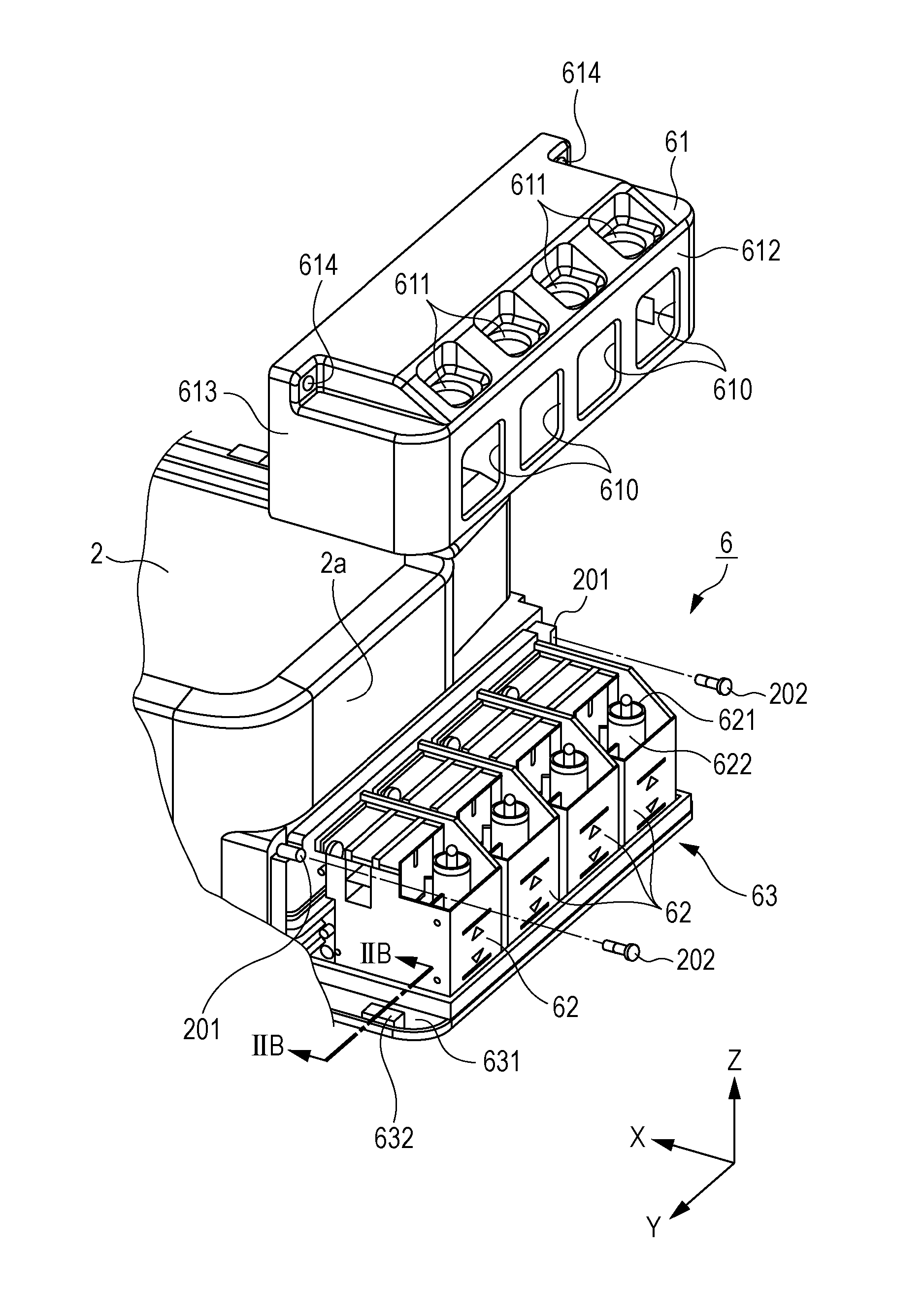
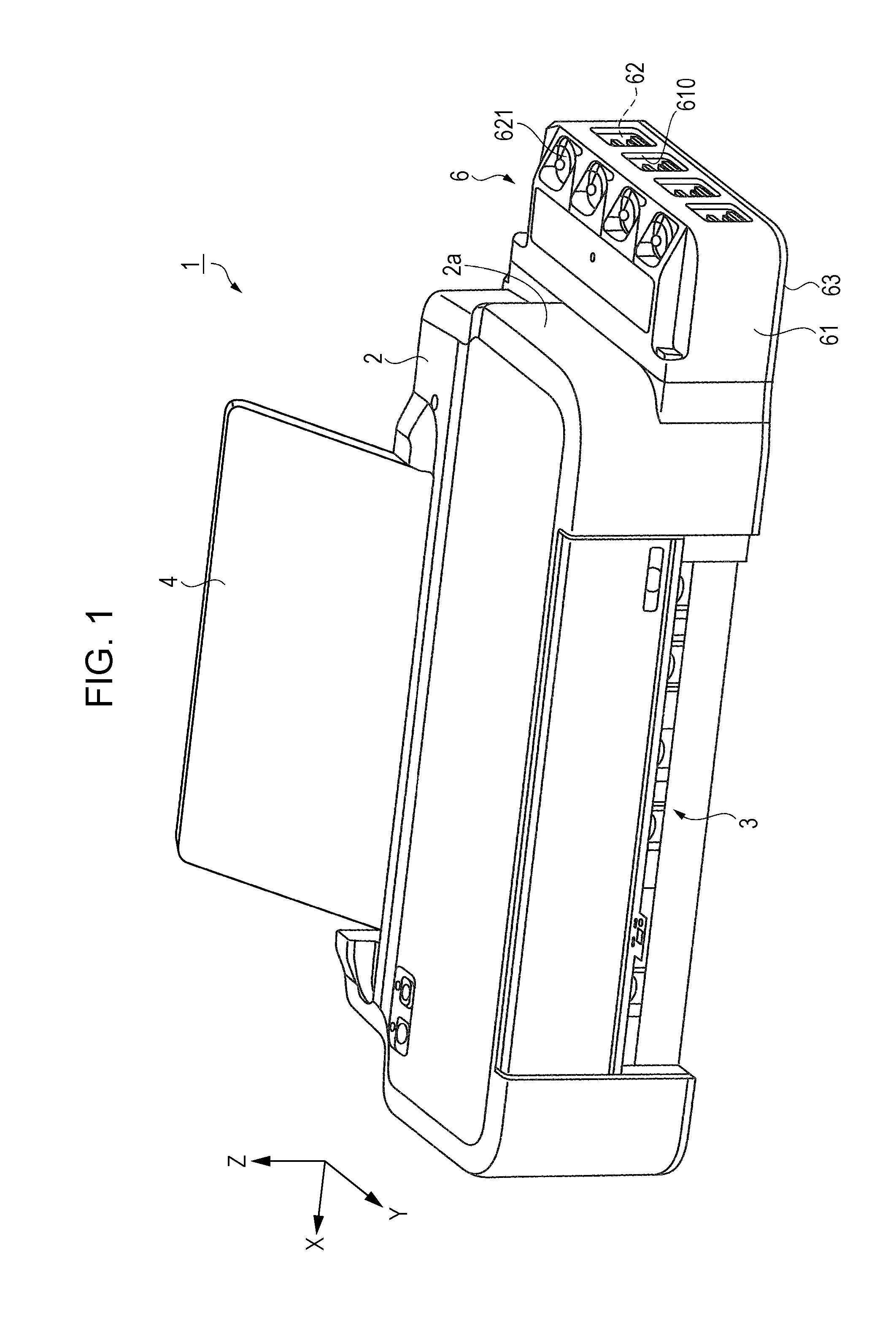
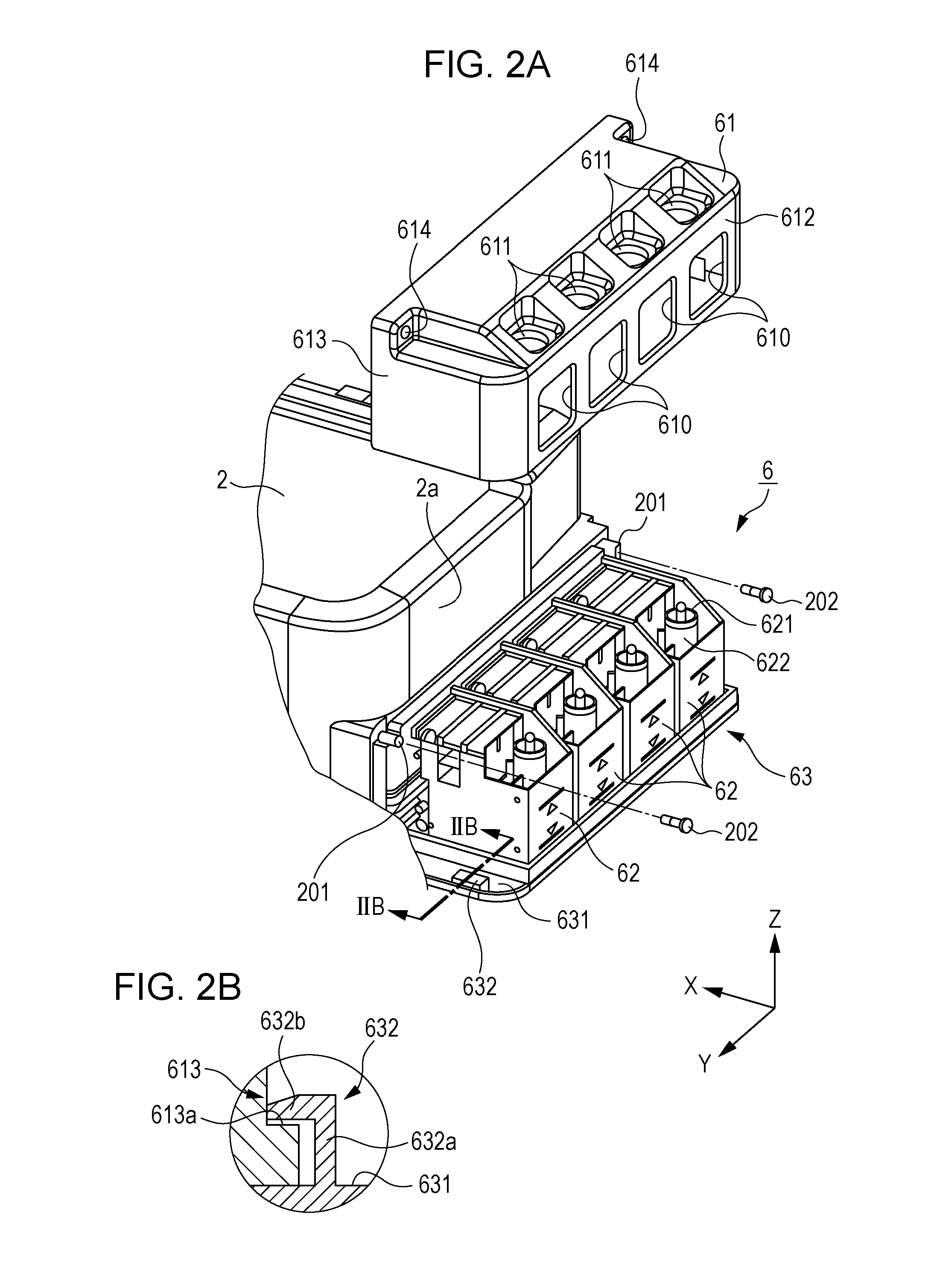
[0038]Hereinafter, an embodiment will be described with reference to the accompanying drawings. In the X-Y-Z orthogonal coordinate system used for illustration in each drawing, an X direction is a movement direction (a main scanning direction) of a carriage, a Y direction is a transporting direction (a sub-scanning direction) of a recording medium, and a Z direction is the gravity direction. The arrow direction in the Y direction indicates a downstream side in the transporting direction and the arrow direction in the Z direction indicates an upper side.

[0039]FIG. 1 is a perspective view of an appearance of an ink jet printer 1 (hereinafter, referred to as a “printer”) as an example of a liquid ejecting apparatus, when seen from a front side. A paper support 4 is provided in a rear side of a case main body 2. The paper support 4 inclinedly supports a paper sheet (not illustrated) as an example of the recording medium. The paper sheets mounted on the paper support 4 are fed to the inn...


PUM


Abstract

Provided is a liquid ejecting apparatus which includes a carriage which reciprocates in a state where a liquid ejecting head is mounted thereon, a tank unit which is provided outside the carriage and accommodates ink, four liquid supply tubes which communicate with the liquid ejecting head and the tank unit, and a tube support portion which supports the liquid supply tubes in a state where the liquid supply tubes are aligned in a horizontal direction, in which, in a case main body, the liquid supply tubes extend further to the tank unit side than a portion in which the liquid supply tubes are supported by the tube support portion, in a state where a parallel alignment direction of the four liquid supply tubes changes from the horizontal direction (a transporting direction) to a vertical direction.

Description

BACKGROUND[0001]1. Technical Field[0002]The present invention relates to a liquid ejecting apparatus.[0003]2. Related Art[0004]In a certain type of a liquid ejecting apparatus which forms an image in such a manner that a carriage having a liquid ejecting head mounted thereon reciprocates and ink is ejected onto a recording medium, such as a paper sheet, an ink tank is provided outside the carriage and a liquid supply tube is provided to supply ink from the ink tank to the liquid ejecting head.[0005]In an ink jet recording apparatus disclosed in, for example, JP-A-2012-152995, a tank unit accommodating an ink tank having ink stored therein is provided in a lateral surface side of an apparatus main body and the ink is supplied to a liquid ejecting head through a liquid supply tube. Downstream-side end portions of a plurality of liquid supply tubes in the apparatus main body are fixed to a carriage and are deformed in accordance with reciprocation of the carriage. Upstream sides of the...

Claims


Application Information

Patent Timeline
Patent Type & Authority Applications(United States)
IPC IPC(8): B41J2/175
CPCB41J2/175B41J2/17509B41J29/02B41J29/13
Inventor KIMURA, NAOMIHAYASHI, KOKISUZUKI, HIDENAOKUDO, SHOMA
Owner SEIKO EPSON CORP
Why Eureka
Try Eureka