Self inflating tire with pressure regulator

Inactive Publication Date: 2015-06-25
THE GOODYEAR TIRE & RUBBER CO
View PDF3 Cites 7 Cited by
  • Summary
  • Abstract
  • Description
  • Claims
  • Application Information

AI Technical Summary

Benefits of technology

[0020]“Sipe” means small slots molded into the tread elements of the tire that subdivide the tread surface and improve traction, s

Problems solved by technology

Accordingly, drivers must repeatedly act to maintain tire pressures or they will see reduced fuel economy, tire life and reduced vehicle braking and hand

Method used


Image

  • Self inflating tire with pressure regulator
  • Self inflating tire with pressure regulator
  • Self inflating tire with pressure regulator

Examples


Example

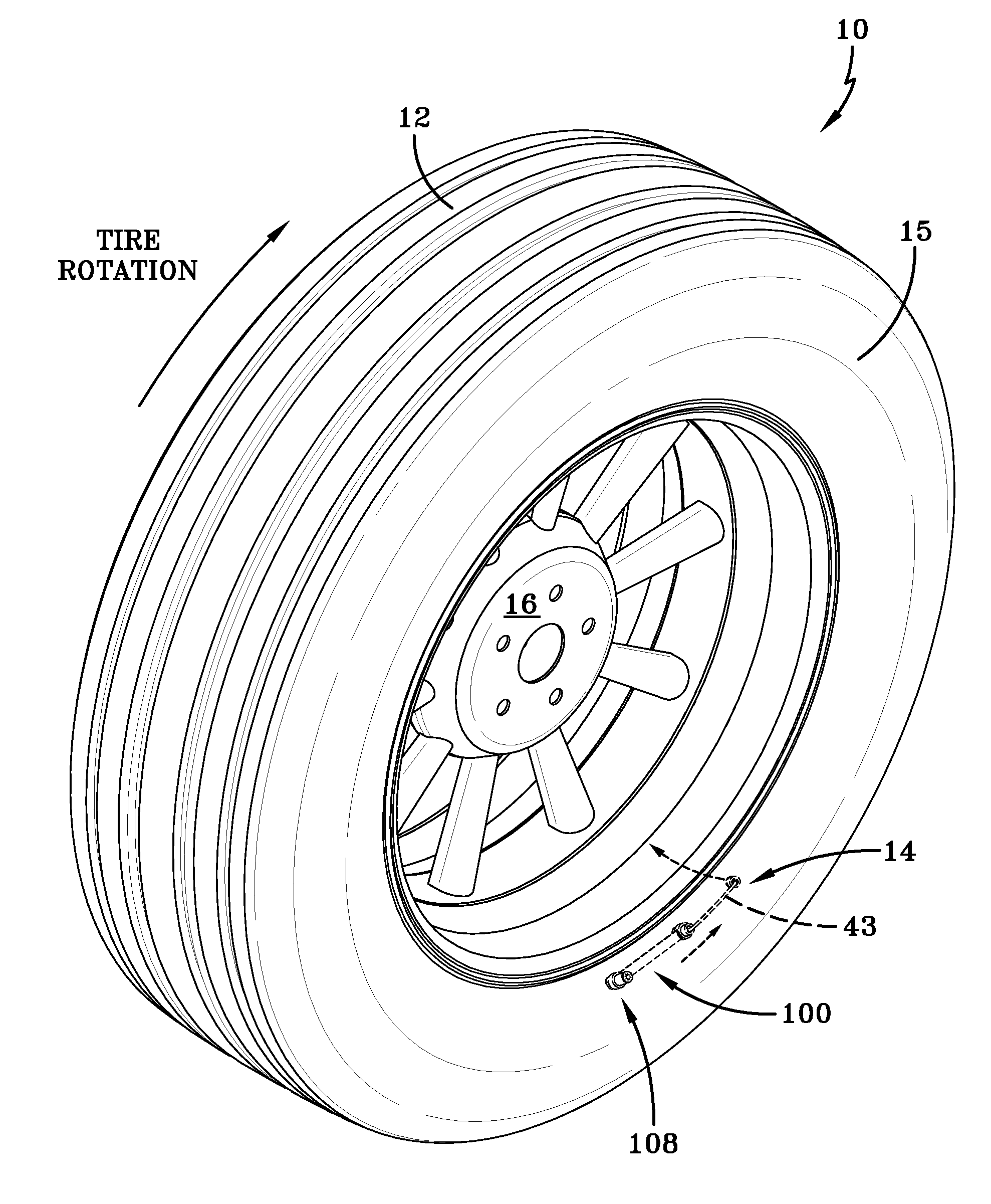
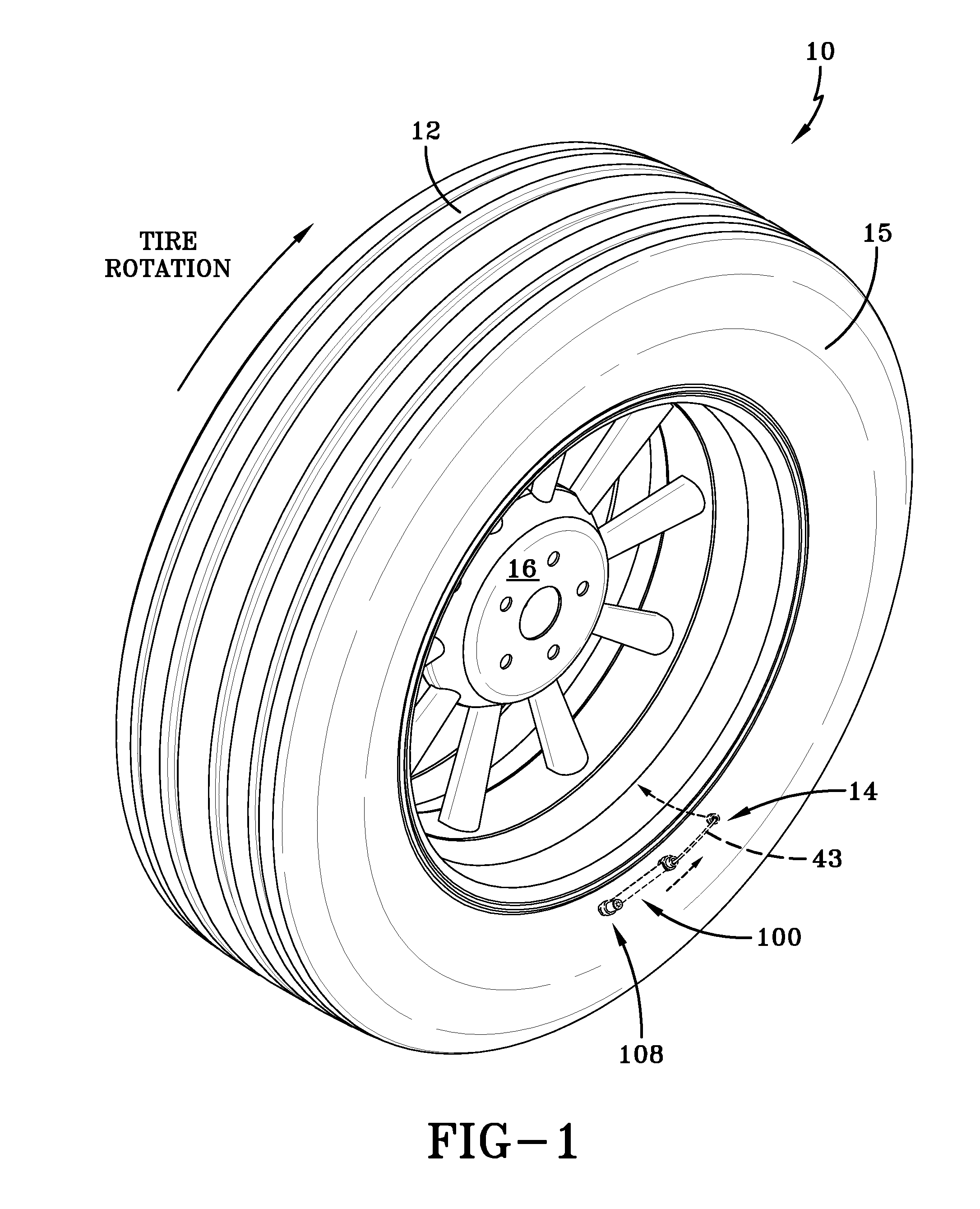
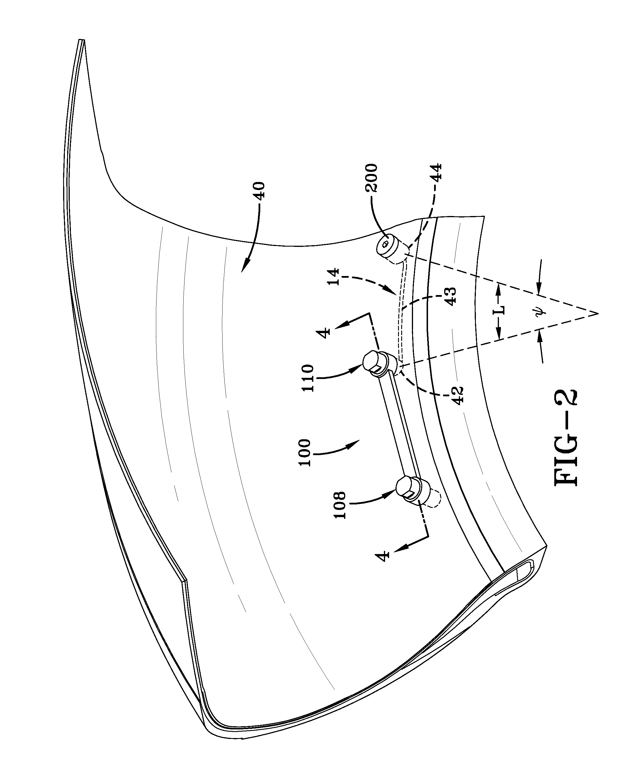
[0031]Referring to FIGS. 1 and 2, a tire assembly 10 includes a tire 12, a pump assembly 14, and a tire rim 16. The tire and rim enclose a tire cavity 40. As shown in FIGS. 1-2, the pump assembly 14 is preferably mounted into the sidewall area 15 of the tire, preferably near the bead region.

Pump Assembly 14

[0032]As shown in FIG. 2, the pump assembly 14 includes an air passageway 43 which may be molded into the sidewall of the tire during vulcanization or formed post cure. When the air passageway is molded into the tire sidewall as shown in FIG. 2, the air passageway has an arc length L as measured by an angle Ψ that is measured from the center of rotation of the tire. In a first embodiment, the angle Ψ may range, and is preferably in the range of about 15-50 degrees or optionally, an angular length sufficient to extend the length of the tire footprint Z, as shown in FIG. 10. The air passageway has an arc length L that may extend in a circumferential direction, or any direction. The ...


PUM


Abstract

A self-inflating tire assembly includes an air tube connected to a tire and defining an air passageway, the air tube being composed of a flexible material operative to allow an air tube segment opposite a tire footprint to flatten, closing the passageway, and resiliently unflatten into an original configuration. The air tube is sequentially flattened by the tire footprint in a direction opposite to a tire direction of rotation to pump air along the passageway to a regulator device. The regulator device regulates the inlet air flow to the air tube and the outlet air flow to the tire cavity.

Description

FIELD OF THE INVENTION[0001]The invention relates generally to self-inflating tires and, more specifically, to a pump mechanism and pressure regulator for such tires.BACKGROUND OF THE INVENTION[0002]Normal air diffusion reduces tire pressure over time. The natural state of tires is under inflated. Accordingly, drivers must repeatedly act to maintain tire pressures or they will see reduced fuel economy, tire life and reduced vehicle braking and handling performance. Tire Pressure Monitoring Systems have been proposed to warn drivers when tire pressure is significantly low. Such systems, however, remain dependent upon the driver taking remedial action when warned to re-inflate a tire to recommended pressure. It is a desirable, therefore, to incorporate a self-inflating feature within a tire that will self-inflate the tire in order to compensate for any reduction in tire pressure over time without the need for driver intervention.SUMMARY OF THE INVENTION[0003]The invention provides in ...

Claims


Application Information

Patent Timeline
IPC IPC(8): B60C23/12B60C19/00B60C5/12
CPCB60C23/12B60C19/00B60C5/12B60C23/123B60C23/135Y10T152/10495
Inventor HINQUE, DANIEL PAUL LUC MARIEPERONNET-PAQUIN, ANNE THERESEBONNET, GILLESPIRET, GAUTHIER
Owner THE GOODYEAR TIRE & RUBBER CO
Why Eureka
Try Eureka