
Covering device with a light source

a technology of light source and cover device, which is applied in the direction of roof, transportation and packaging, light and heating apparatus, etc., can solve the problems of limited embodiment, raised reliability issues, and the solution is therefore not applicable when the support is completely movabl

Active Publication Date: 2015-06-25
WEBASTO AG
View PDF3 Cites 12 Cited by
  • Summary
  • Abstract
  • Description
  • Claims
  • Application Information

AI Technical Summary

Benefits of technology

The patent describes a device that uses optical fibers to scatter light and provide illumination in a distributed manner. The device includes a covering unit that can be moved to scatter light, while a fixed light source provides power to the optical fibers. The optical fibers have lateral scattering, meaning the light is emitted along their length rather than just at the end. This allows for illumination of the entire surface covered by the optical fibers. The device also includes a beam waveguide that uses a single light source to scatter light along the rail, and screening means to prevent excessive lighting and mask the effect of the illumination. Overall, the device provides a more uniform and effective distribution of light compared to traditional lighting systems.

Problems solved by technology

An embodiment of this type requires the fastening of a generally rigid light source on a flexible element, which raises reliability issues.
Moreover, said embodiment is limited to cases in which the electrical supply to the light source can be implemented, that is to say to those cases in which the flexible element has a part which is fastened on the body.
This solution is consequently not applicable when the support is completely movable, as is the case in the previously mentioned covering units.
However, the illumination is limited to the peripheries of the device.

Method used


Image

  • Covering device with a light source
  • Covering device with a light source
  • Covering device with a light source

Examples


first embodiment

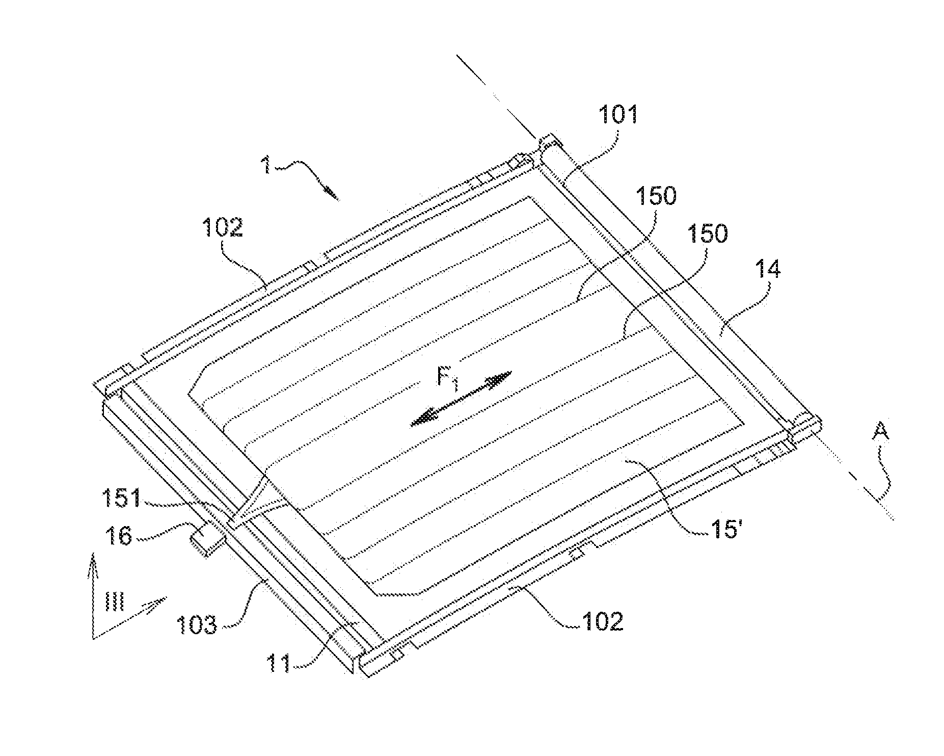
[0023]FIG. 1 shows a perspective view from above of a covering device according to the invention, wherein a covering unit is in the expanded position;

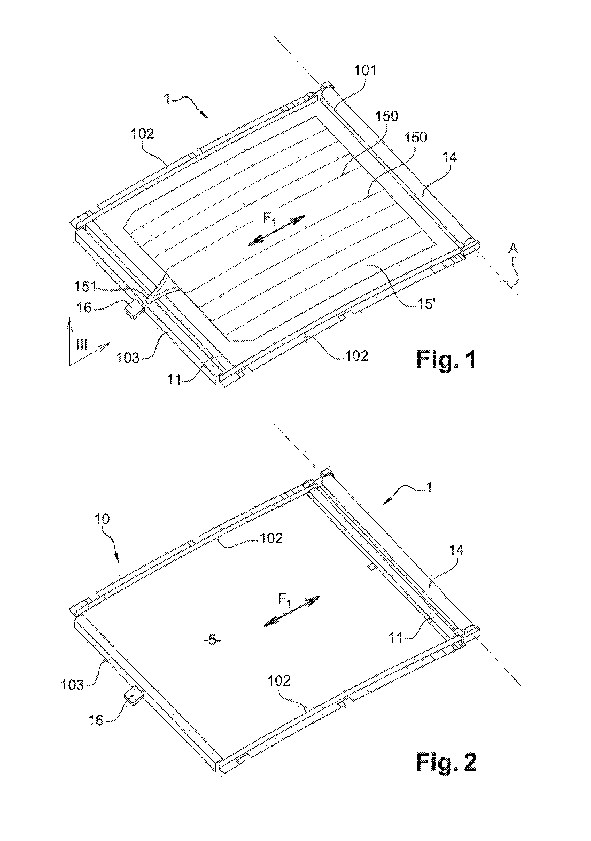
[0024]FIG. 2 shows a view which is similar to that of FIG. 1, wherein the covering unit is in the storage position;

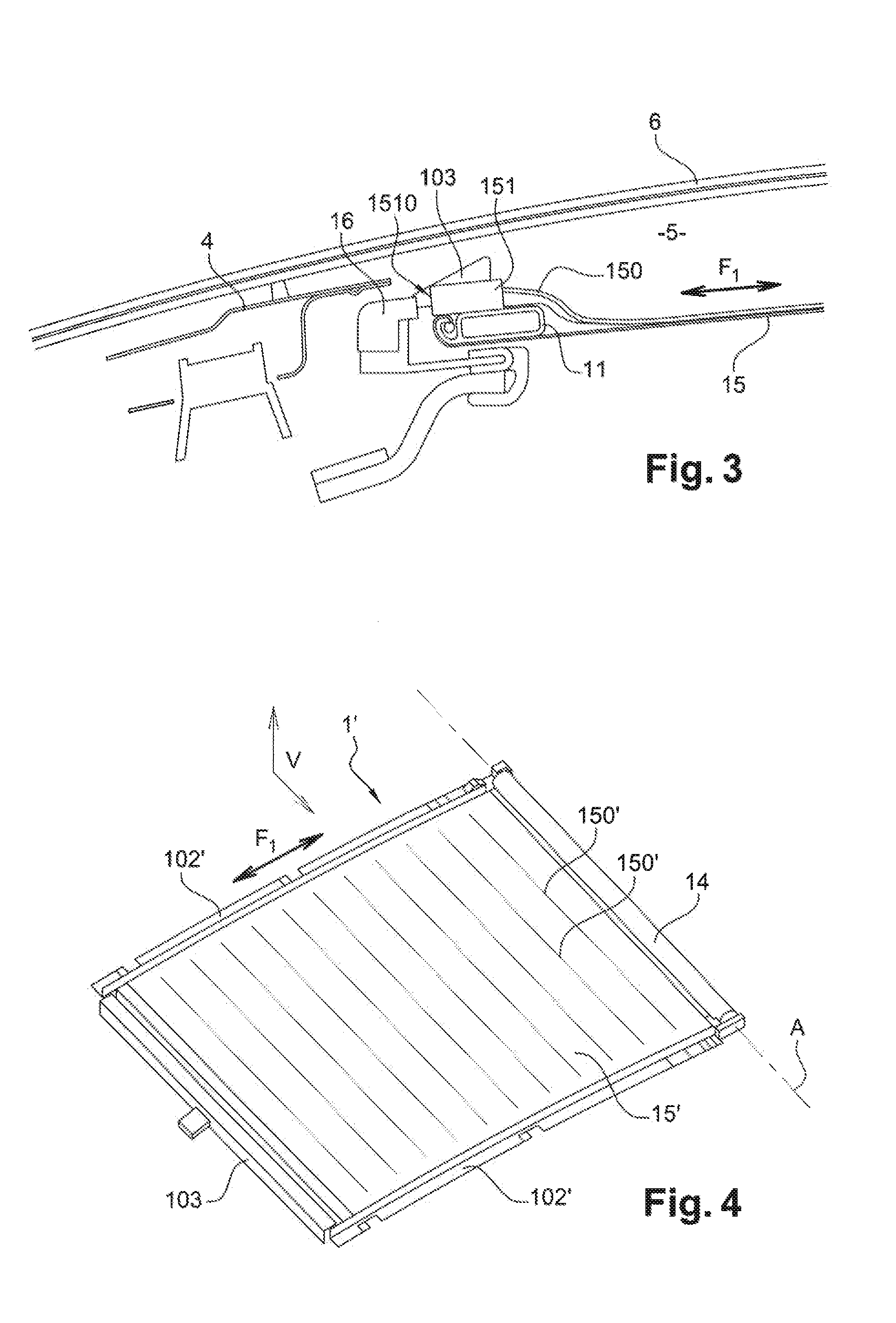
[0025]FIG. 3 shows a sectional view according to plane III of FIG. 1, showing the covering device in place beneath the car roof of a vehicle;

second embodiment

[0026]FIG. 4 shows a view, which is similar to that of FIG. 1, of the invention;

[0027]FIG. 5 shows a sectional view according to plane V of FIG. 4;

third embodiment

[0028]FIG. 6 shows a view, which is similar to that of FIG. 1, of a device according to the invention.

DETAILED DESCRIPTION OF EXEMPLARY EMBODIMENTS

[0029]A covering device 1 according to an embodiment as shown in FIGS. 1 to 3 comprises a frame 10 which is to be fastened beneath the car roof 4 of a vehicle, opposite a paned opening 5 having, for example, a fixed glass panel 6. The directions used in this description refer to those which relate to the vehicle in a usual position when in use. The frame 10 comprises two lateral rails 102, in which a pull rod 11 is displaced between an expanded position, such as illustrated in FIG. 1, and a storage position, such as illustrated in FIG. 2. The rearward cross member 101 comprises a winding-up device 14 which extends along the entire length of the rearward cross member 101. The winding-up device 14 is rotatably attached about a winding-up device axis A, and a web 15 is wound up onto the winding-up device 14. The web 15 which forms a covering...


PUM


Abstract

A covering device to be fastened opposite an opening of a motor vehicle and comprises at least one element which is fastened on the circumference of the opening, wherein a covering unit is displaced in an expansion direction between a storage position, in which the covering unit is released from the opening, and a covering position, in which the covering unit is extended opposite the opening, wherein the covering unit comprises a network of optical fibers having lateral light scattering. The network of optical fibers is supplied with light by at least one light source which is fastened on the element and, in order to supply the network of optical fibers with light, can illuminate ends of the optical fibers of the network in at least one illuminating position of the covering unit.

Description

TECHNICAL FIELD[0001]The present invention relates to a covering device having a light source. In particular, said covering device has an application in devices which are integrated in a motor vehicle.PRIOR ART[0002]The motor vehicles are often equipped with an opening which is configured in the car roof, wherein the opening is closed off by a transparent panel in order to allow light to enter the interior of the passenger cabin. The transparent panel, for example of glass, may be installed in a fixed or movable manner, so as to enable the opening to be at least partially exposed. The potential for the user of covering this opening with the aid of a covering device is also created.[0003]A covering device according to a special type comprises a winding-up device onto which a web is wound up. A pull rod is fastened along a periphery of the web, parallel to the axis of the winding-up device, and tensioning means for tensioning the web between the pull rod and the winding-up device are ...

Claims


Application Information

Patent Timeline
IPC IPC(8): B60Q3/00B60Q3/02B60J7/00
CPCB60Q3/005B60Q3/0203B60J7/0015B60J7/0007B60Q3/208B60Q3/64B60Q3/51B60Q3/66
Inventor ALBERT, JEAN-PAUL
Owner WEBASTO AG
Learn More