Sandglass type ocean engineering floating structure

Active Publication Date: 2015-06-25
DALIAN UNIV OF TECH
View PDF2 Cites 9 Cited by
  • Summary
  • Abstract
  • Description
  • Claims
  • Application Information

AI Technical Summary

Benefits of technology

[0016]Due to the adoption of the technical scheme, the ocean engineering floating structure provided by the present invention is implemented by virtue of a simple structure; and the ocean engineering floating structure has a relatively large oil storage space compared with the traditional drilling and production platform and better movement performance compared

Problems solved by technology

However, owing to limited bearing capability and relatively small hold capacity space, the semi-submersible floating structure will limit storage of large-scale oil and gas and installation of essential equipment and produce the problem of uneven load distribution caused by occupancy to a large amount of deck area even though a method of configuring an oil tank is adopted.
Therefore, it is very difficult for the traditional semi-submersible floating structure to realize integration of large-scale oil and gas production, storage, production, processing and transport.
This kind of structures can be configured for deepwater oil and gas development and have movement stability and favorable safety, however, its shortages are that deep draught is greatly affected by ocean current, the structures are very difficult to haul and volumes for accommodating equipment and storing oil and gas and the deck area are very small, all of which limit the develop of multifunctional integration of such structures on different levels.
However, those ship-like floating bodies have some limitations and shortages in the hydrodynamic performance as follows:
Besides, the ship-like FPSO is very sensitive to the action direction of waves and has overlarge area of transverse motion in heading sea, t

Method used


Image

  • Sandglass type ocean engineering floating structure
  • Sandglass type ocean engineering floating structure
  • Sandglass type ocean engineering floating structure

Examples


Embodiment Construction

[0022]The technical solution in the embodiments of the present invention is described clearly and completely in conjunction with the accompanying drawings in the embodiments of the present invention in order to make the objective, the technical solution and the advantages of the present invention clearer:

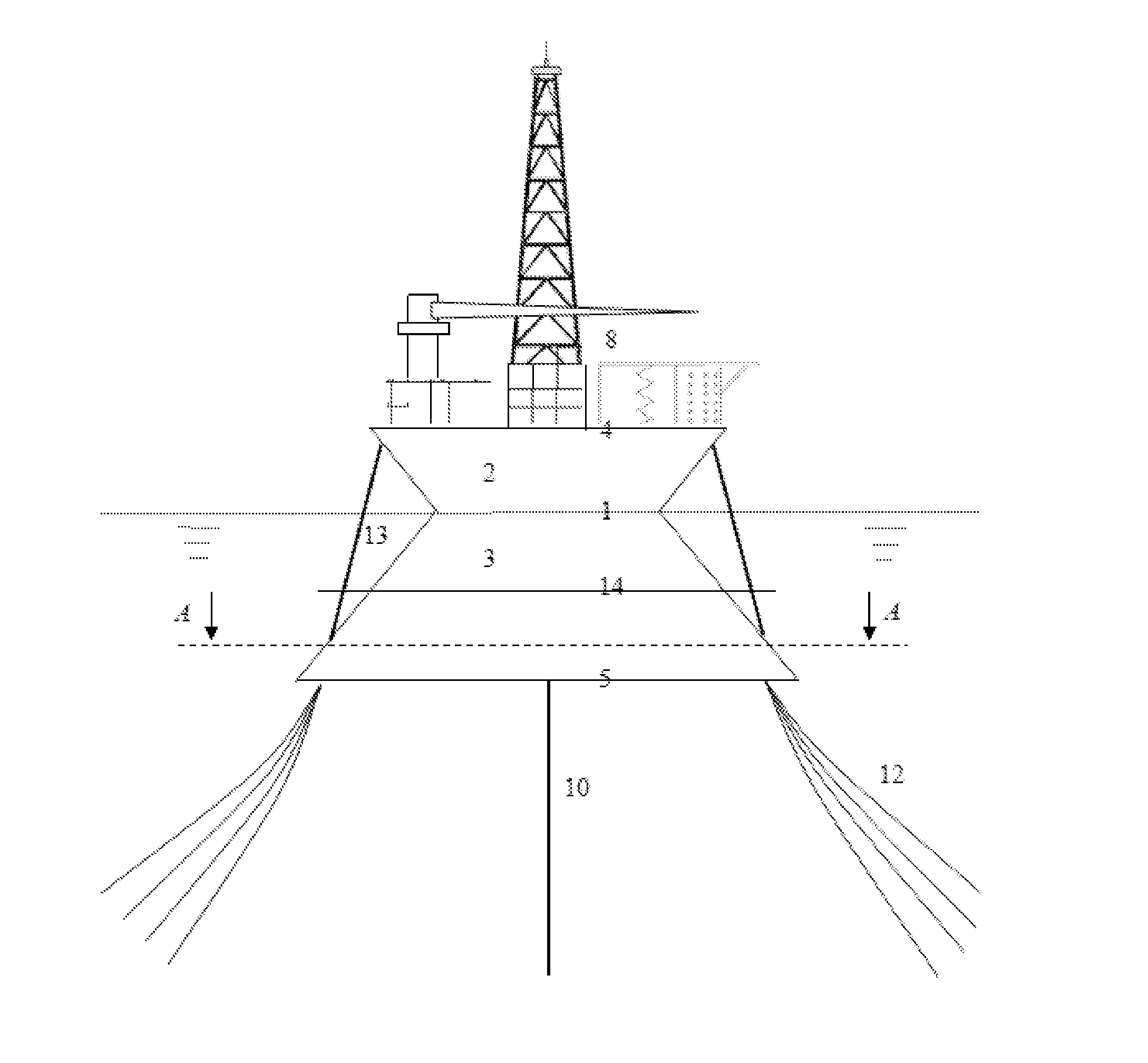
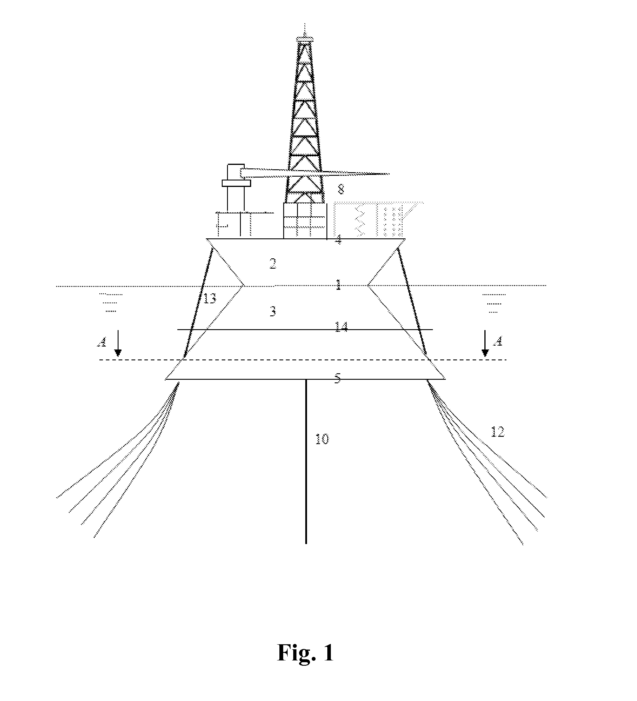
[0023]As shown in FIG. 1, an ocean engineering floating structure has a shape similar to a sandglass, that is, has an upper bottom surface and a lower bottom plate surface which are parallel to each other, which act as an upper deck 4 of the structure and a bottom plate 5 underwater, respectively, wherein the diameter of the middle part of the structure main body is remarkably smaller than the diameters of other parts, thus forming a structure similar to wasp waist or narrow waist.

[0024]As a preferable embodiment, the ocean engineering floating structure mainly comprises two parts, namely the upper structural body 2 shaped as a circular truncated cone or frustum and a lower structur...


PUM


Abstract

A sandglass type ocean engineering floating structure is provided with an upper structural body shaped as a circular truncated cone or frustum and a lower structural body shaped as a regular circular truncated cone or regular frustum; under a combined state, the smaller bottom surface of the upper structural body is fixedly connected with the smaller bottom surface of the lower structural body to form a junction surface; the axis of the upper structural body and the axis of the lower structural body are positioned on the same straight line; the larger bottom of the upper structural body acts as an upper deck of the floating structure and the larger bottom of the lower structural body acts as a lower plate underwater of the floating structure; the junction surface is a full-load waterplane of the floating structure.

Description

TECHNICAL FIELD[0001]The present invention relates to a ship (patent classification No: B63) or other waterborne vessels; a ship having ship-related equipment B63B and other waterborne vessels; and shipborne equipment B63B35 / 00 suitable for ships for special purposes or similar floating buildings having a floating structure B63B35 / 44, waterborne cabins, waterborne drilling platforms or waterborne workshops, for instance, which are loaded with oil-water separation equipment.BACKGROUND ART[0002]In the ocean engineering field, no matter from the points of economy of oil and gas production in shallow water areas and necessity of oilfield development in deepwater and superdeep water areas, corresponding scale of floating structures are required to be used. Besides, with the trends of multifunctional integration and development toward deep sea, the floating structures not only need enough hold capacity and deck area to bear oil and gas and equipment necessary to develop and produce, but n...

Claims


Application Information

Patent Timeline
IPC IPC(8): B63B35/44B63B3/20
CPCB63B35/4413B63B3/20B63B2003/147B63B35/08
Inventor HUANG, YIWANG, WENHUAYAO, YUXINLIU, GANGZHANG, QILI, HONGXIACHEN, JINGJIEZHAI, GANGJUN
Owner DALIAN UNIV OF TECH
Why Eureka
Try Eureka