

Involute line screw tooth shape of large flow double screw pump
A twin-screw pump, involute technology, used in pumps, rotary piston pumps, rotary piston machines, etc., can solve the problems of small specific flow and large volume, achieve high pressure, large oil storage space, shorten the screw effect of length
- Summary
- Abstract
- Description
- Claims
- Application Information
AI Technical Summary
Problems solved by technology
Method used
Image

Examples
Embodiment Construction
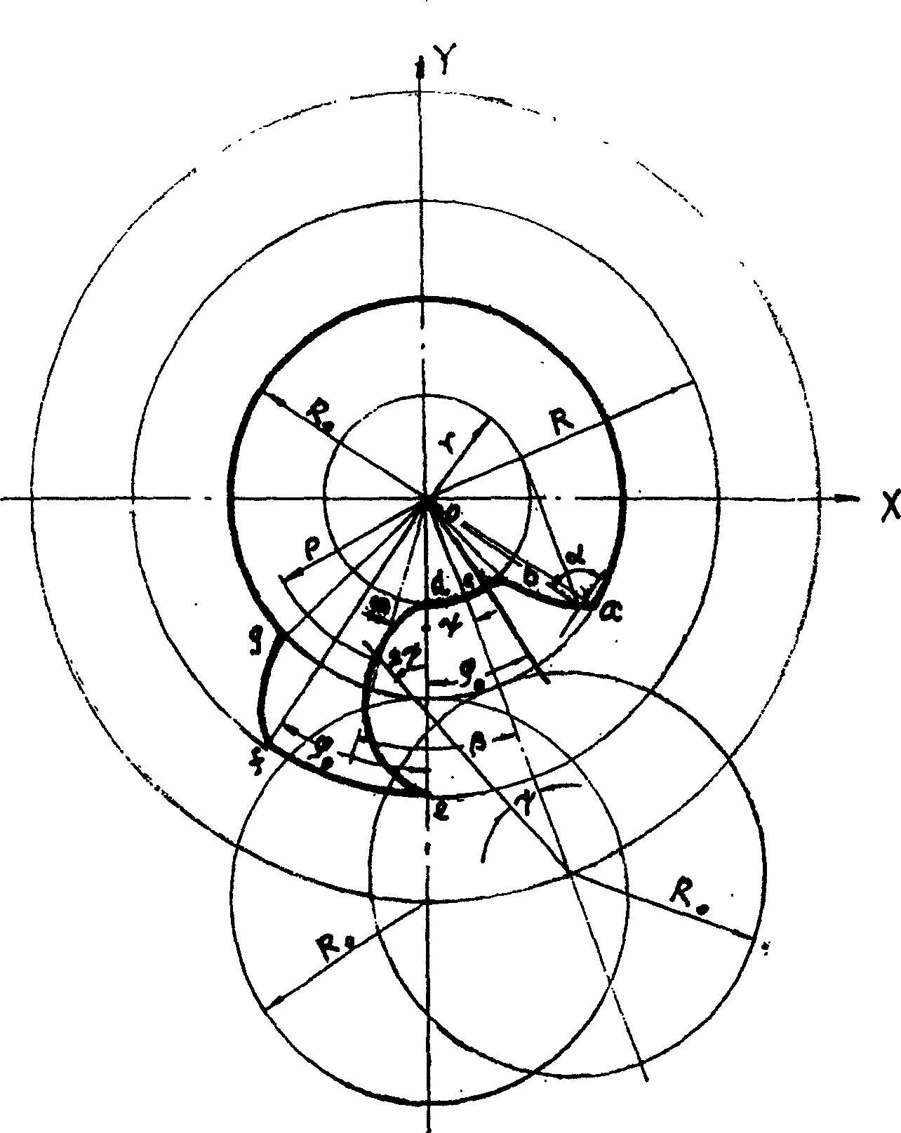
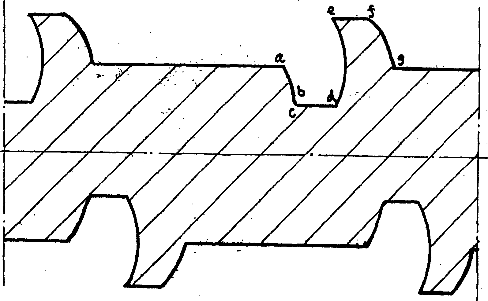
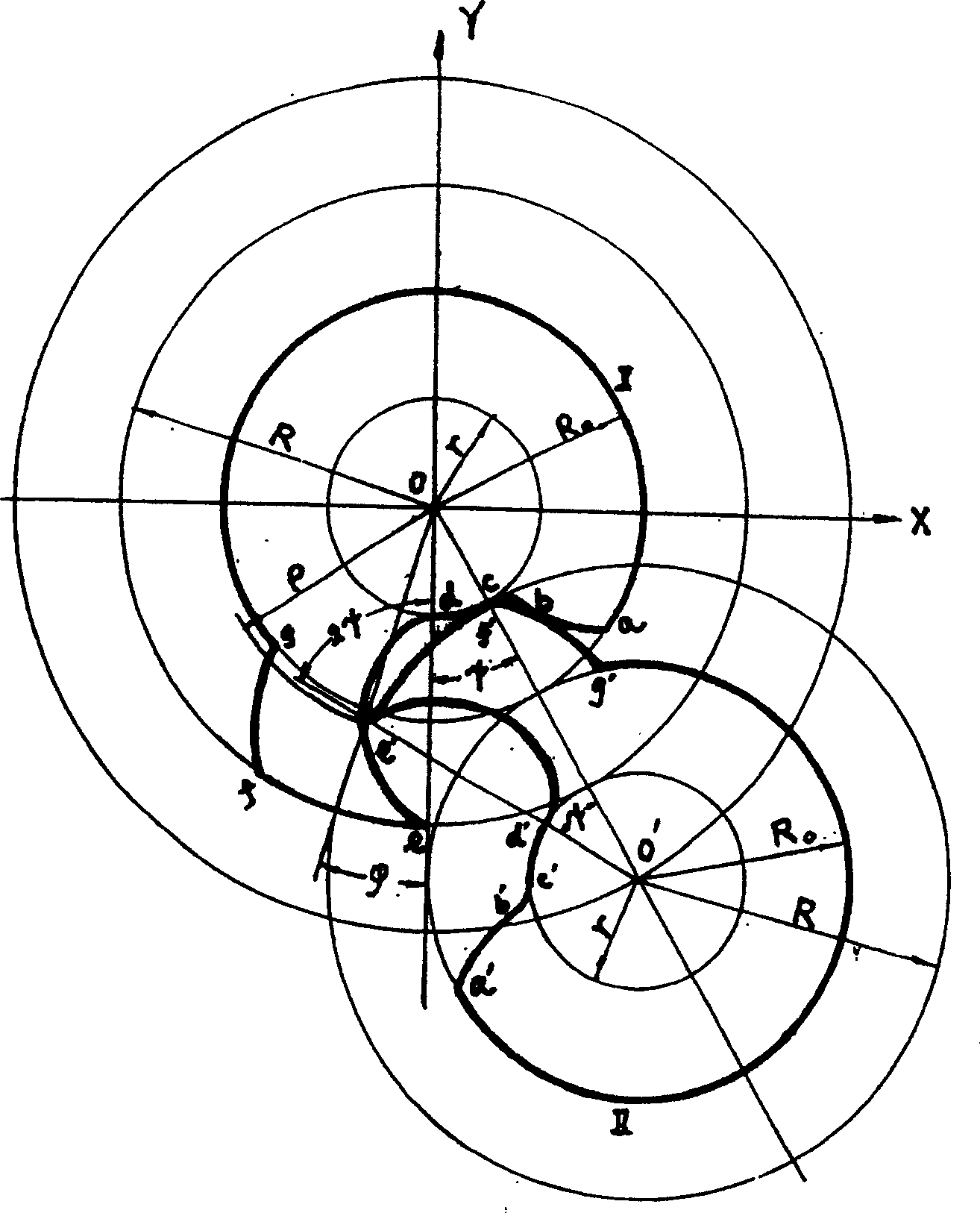
[0015] The shape of the radial section of the screw, the addendum circle curve is a circular arc line, the dedendum circle curve on the opposite side of the addendum circle is a circular arc line, and the pitch circle curve on the middle side of the addendum circle and the dedendum circle is a circular arc line , the one end point of the dedendum circular solitary line and the one end point of the dedendum circular solitary line are composed of extended cycloids, the distance between the other end point of the dedendum circular solitary line and the first end point of the pitch circle solitary line is composed of extended cycloids, and the addendum circular solitary line An epicycloid is formed between the other end point of the line and the other end point of the pitch circle solitary line; the number of heads of the screw is n≥1, and the length of the screw is greater than the length of two pitches.
[0016] The present invention will be described in detail below in conjuncti...
PUM
 Abstract
Description
Claims
Application Information