Precision tool for locating center lines in geometric shapes

a technology of center lines and precision tools, applied in the direction of instruments, measurement devices, using mechanical means, etc., can solve the problems of limited instruments in several ways

Active Publication Date: 2015-06-25
JAMES J DANKOWSKI TRUST
View PDF14 Cites 2 Cited by
  • Summary
  • Abstract
  • Description
  • Claims
  • Application Information

AI Technical Summary

Benefits of technology

[0009]To precisely define the center line of a geometric shape, the base leg is maintained in a particular orientation relative to the two positioning legs. The base leg is restricted to maintaining an orientation in which the base leg bisects the angle formed by its two flanking positioning legs. As the positioning legs move outward from the base leg (or inward toward it), the first positioning leg forms an angle with the base leg that is the same as the angle formed by the second positioning leg and the base leg. This feature ensures the mathematical precision of the center line identified by the disclosed invention.
[0011]One embodiment of the invention further comprises a central leg. The central leg provides means to maintain the positioning legs in a particular orientation relative to the base leg, so that the precision tool accurately identifies the center line between the two separate points on the edge of a geometric shape that are indicated with the positioning legs.
[0012]Another embodiment of the invention further comprises a simple planetary gear system, instead of a central leg, to ensure that the positioning legs maintain the correct orientation relative to the base leg. In this way, the base leg and positioning legs maintain the necessary orientation so that the precision tool accurately identifies the center line between two separate points on the edge of a geometric shape. The planetary gear system provides an alternative means of adjusting the positioning legs to maintain the required orientation relative to the base leg.

Problems solved by technology

Precision tools exist that can be used to identify the center lines of different geometric shapes, but those instruments are limited in several ways.

Method used


Image

  • Precision tool for locating center lines in geometric shapes
  • Precision tool for locating center lines in geometric shapes
  • Precision tool for locating center lines in geometric shapes

Examples


embodiment 1

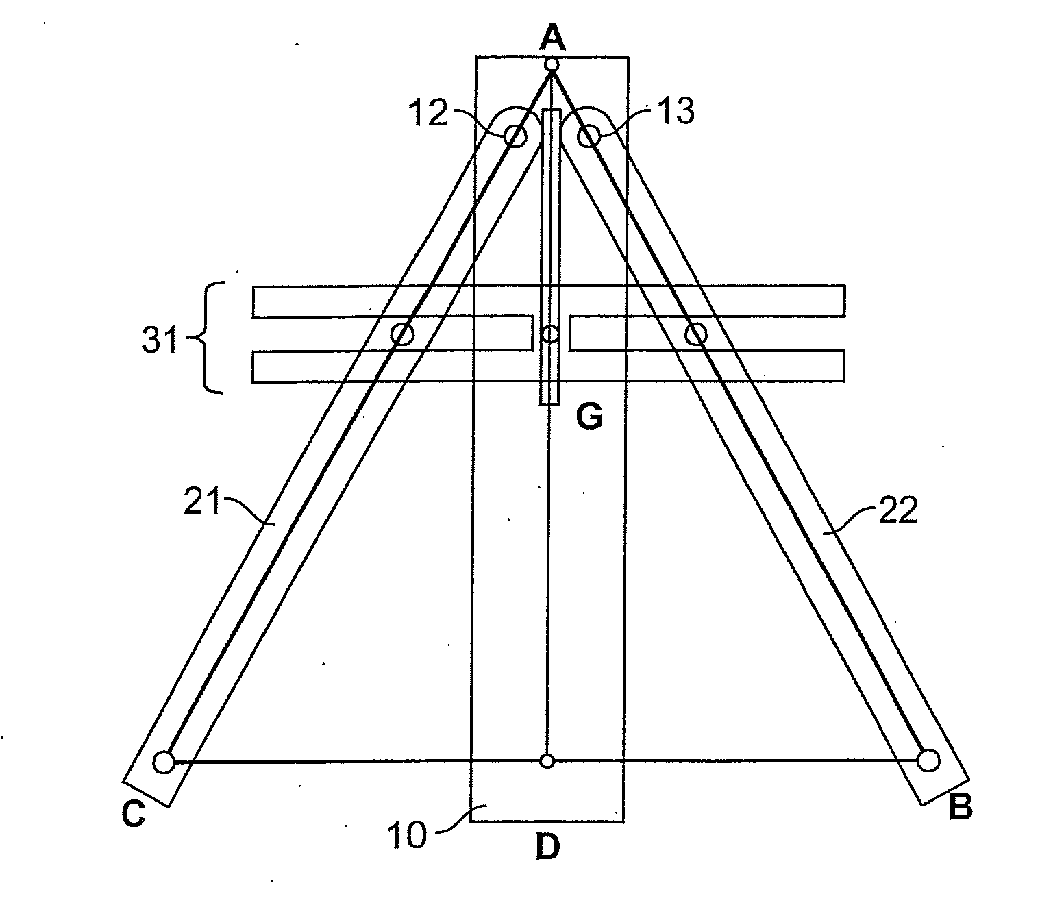
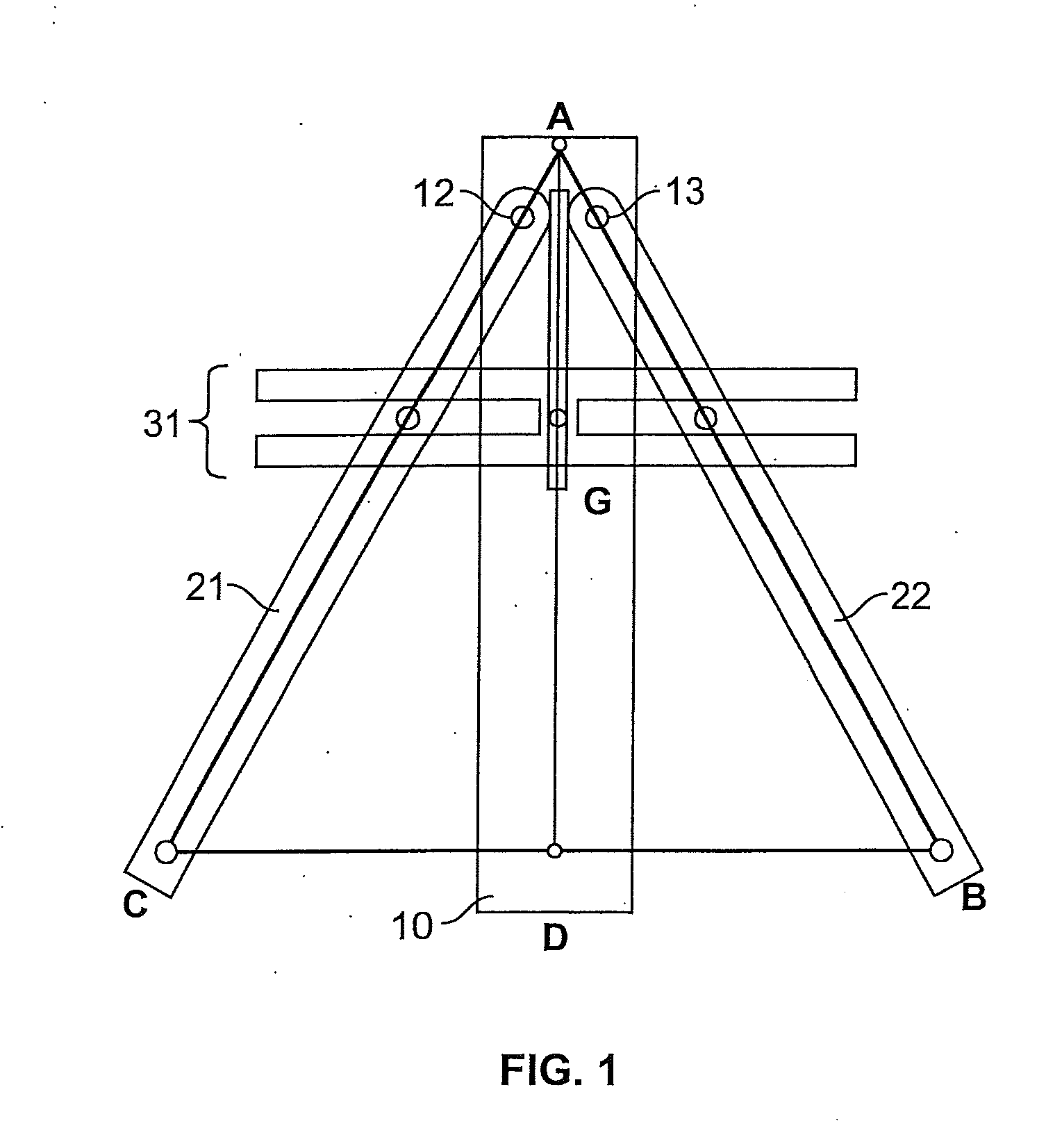
[0025]FIGS. 1-6 illustrate one embodiment of a precision tool of the disclosure. The embodiment shown in FIGS. 1-2 includes a base leg 10, two positioning legs 21, 22 attached next to each other atop the base leg 10, and a central leg 31 atop the two positioning legs 21, 22.

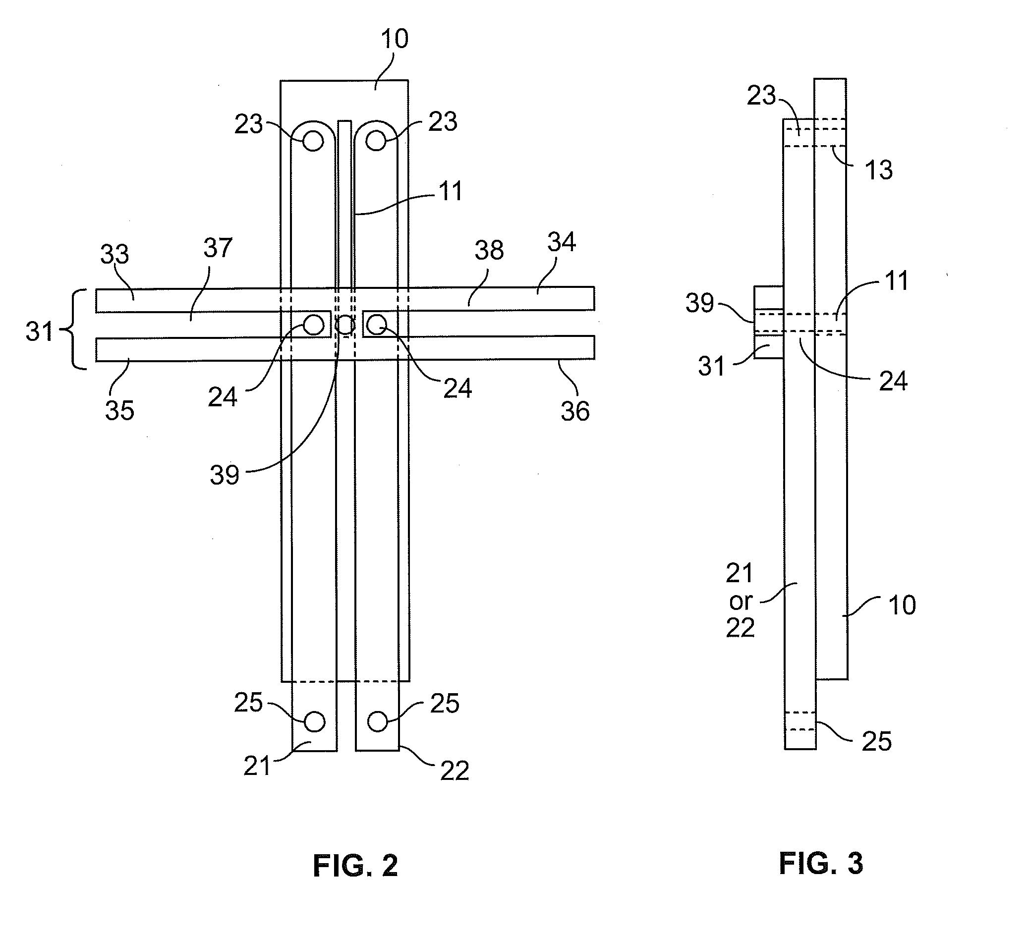
[0026]The base leg 10 is shown in greater detail in FIGS. 6A-6B. The base leg 10 contains a thru slot 11 positioned in its midline and four openings 12-15.

[0027]The two positioning legs 21, 22 are identical in structure and shown in greater detail in FIGS. 4A-4B. Each positioning leg 21, 22 has three openings 23-25. The first positioning leg 21 is slidingly attached atop the base leg 10 by a fastening means through opening 12 of the base leg 10 and opening 23 of the first positioning leg 21. The second positioning leg 22 is slidingly attached atop the base leg 10 by a fastening means through opening 13 of the base leg 10 and opening 23 of the second positioning leg 22.

[0028]The first positioning leg 21 slidingly ...

embodiment 2

[0035]FIG. 7 illustrates an example of an alternative embodiment of a precision tool of the disclosure. In this embodiment, the relative alignment of the base leg and two positioning legs are maintained by means of simple planetary gear system, instead of the central leg piece described in Embodiment 1.

[0036]This precision tool is made of a base leg 60, a first positioning leg 70, and a second positioning leg 80 that are aligned by a simple planetary system. The simple planetary system has a sun gear 71, planet gear 61, curved groove 72, and ring gear 82.

[0037]The base leg 60 forms the bottom piece of the precision tool. The planet gear 61 is attached atop the base leg 60 near the base leg's apex. The planet gear 61 is attached at point 62 so that the planet gear can only rotate around its own center.

[0038]First positioning leg 70 contains a curved groove 72 near its apex. A sun gear 71 is fastened atop first positioning leg 70, positioned closer to the apex than the curved groove 7...

embodiment 3

[0043]FIGS. 8A-8B illustrate an example of an alternative embodiment of a precision tool of the disclosure. In this embodiment, the relative alignment of the base leg and two positioning legs are maintained by means of gears, instead of the central leg piece described in Embodiment 1 or the simple planetary gear system described in Embodiment 2.

[0044]This precision tool is made of a base leg 91, a first positioning leg 92, and a second positioning leg 93 that are aligned with gears 94, 95. The first positioning leg 92 is slidingly attached atop the base leg 91 near its apex by means of a gear 94 sandwiched between them. The second positioning leg 93 is slidingly attached atop the base leg 91 near its apex by means of a gear 95 sandwiched between them. Gear 94 is identical to gear 95 and the teeth of the two gears contact each other. The first positioning leg 92 and second positioning leg 93 are the same length.

[0045]The gears function to restrict the movement of the first positionin...


PUM


Abstract

The disclosed invention relates to easy-to-use precision tools that locate the mid-line, or center line, of any symmetrical geometric shape, such as triangles, squares, circles, rectangles, parallelograms, trapezoids, and symmetrical polygons. Given two separate points on the edge of a symmetrical geometric shape, these precision tools identify the center line of the geometric shape between those two points, without the need for additional measurements or mathematical calculations. The precision tools can also be used to identify the center points of symmetrical geometric shapes.

Description

FIELD[0001]This invention relates to simple, easy-to-use precision tools that precisely locate the mid-line, or center line, of any symmetrical geometric shape, such as squares, circles, rectangles, parallelograms, and trapezoids. The invention is a single object wherein contact members locate or check the center of a hole or the location of a center line, without the need for measurements or mathematical calculations.BACKGROUND OF THE INVENTION[0002]There is a need for a simple-to-use, precision tool that accurately identifies the center lines and center points of a variety of geometric shapes, requiring no more than simple manual manipulations by the user to determine the center lines with mathematical precision.[0003]Precision tools exist that can be used to identify the center lines of different geometric shapes, but those instruments are limited in several ways. Similar instruments that are easy to operate incorporate sophisticated construction or automation to identify center ...

Claims


Application Information

Patent Timeline
Patent Type & Authority Applications(United States)
IPC IPC(8): G01B5/14
CPCG01B5/14G01B3/00
Inventor DANKOWSKI, JAMES
Owner JAMES J DANKOWSKI TRUST
Why Eureka
Try Eureka