Motor control apparatus for controlling motor to drive output shaft with positioning accuracy unaffected by backlash in rotation transmission system

a technology of motor control and output shaft, which is applied in the direction of motor/generator/converter stopper, dynamo-electric converter control, instruments, etc., can solve the problem of inability to accurately control the output shaft, and achieve the effect of increasing durability, accurate control, and increasing accuracy

Active Publication Date: 2005-08-11
DENSO CORP
View PDF10 Cites 59 Cited by
  • Summary
  • Abstract
  • Description
  • Claims
  • Application Information

AI Technical Summary

Benefits of technology

[0009] It is an objective of the present invention to overcome the above problems of the prior art, by providing a motor control apparatus for application to a system having a rotation transmission system that couples a motor to a control object such as a shift position switching mechanism and that has some degree of backlash, whereby it becomes unnecessary for the apparatus to perform a learning operation prior to driving the control object before beginning to drive the control object, while enabling an amount of actuation of the control object to be accurately controlled, without that amount of actuation being affected by the backlash that is present in the rotation transmission system. The invention can thereby provide a motor control apparatus having increased accuracy of control, increased durability, and enabling more rapid actuation of the control object.

Problems solved by technology

So long as the effects of backlash are occurring during motor rotation, the relationship between successive rotation angles of the motor shaft and the rotation angle of the output shaft is undefined, so that accurate control of the output shaft is impossible.

Method used


Image

  • Motor control apparatus for controlling motor to drive output shaft with positioning accuracy unaffected by backlash in rotation transmission system
  • Motor control apparatus for controlling motor to drive output shaft with positioning accuracy unaffected by backlash in rotation transmission system
  • Motor control apparatus for controlling motor to drive output shaft with positioning accuracy unaffected by backlash in rotation transmission system

Examples


second embodiment

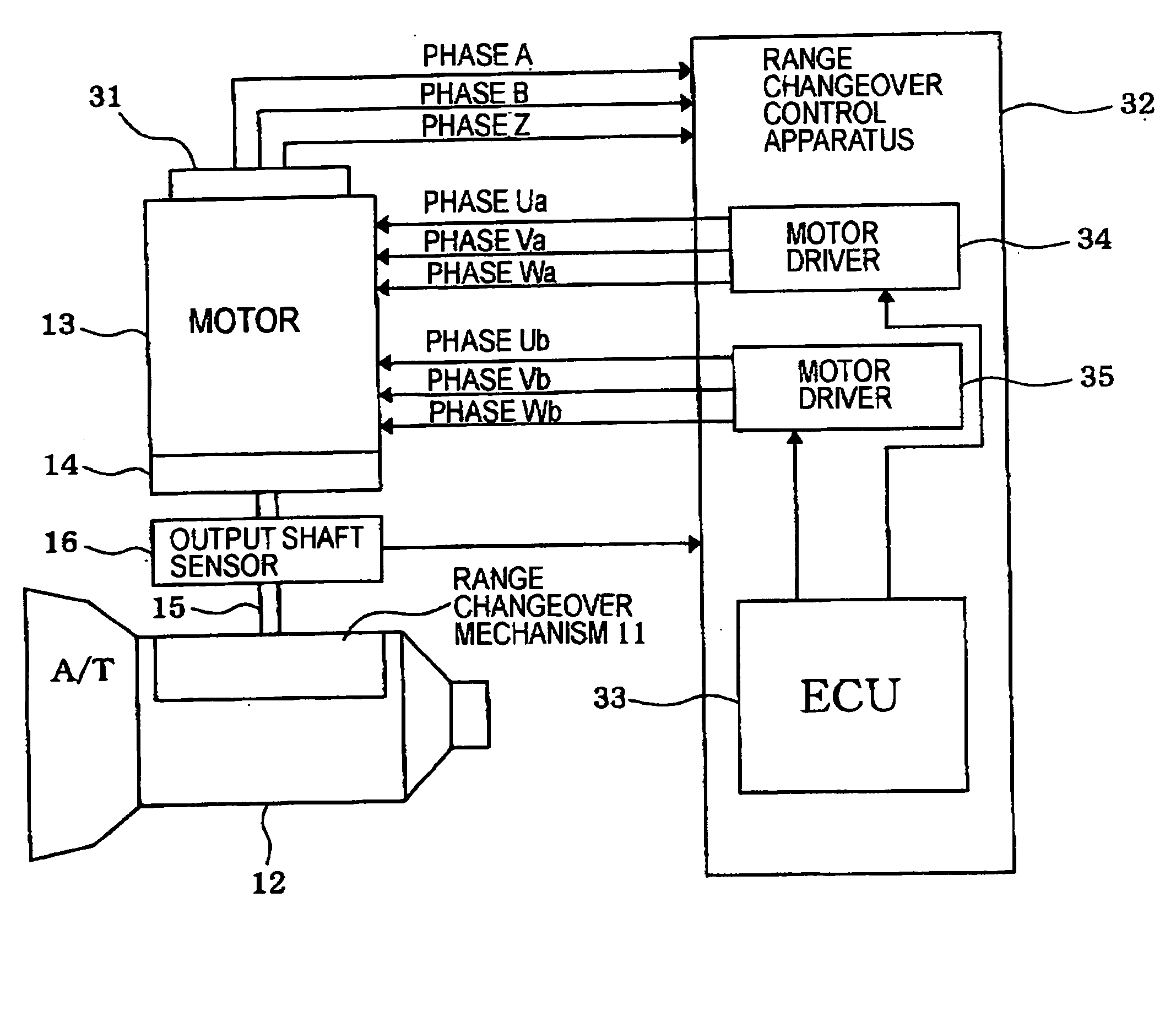
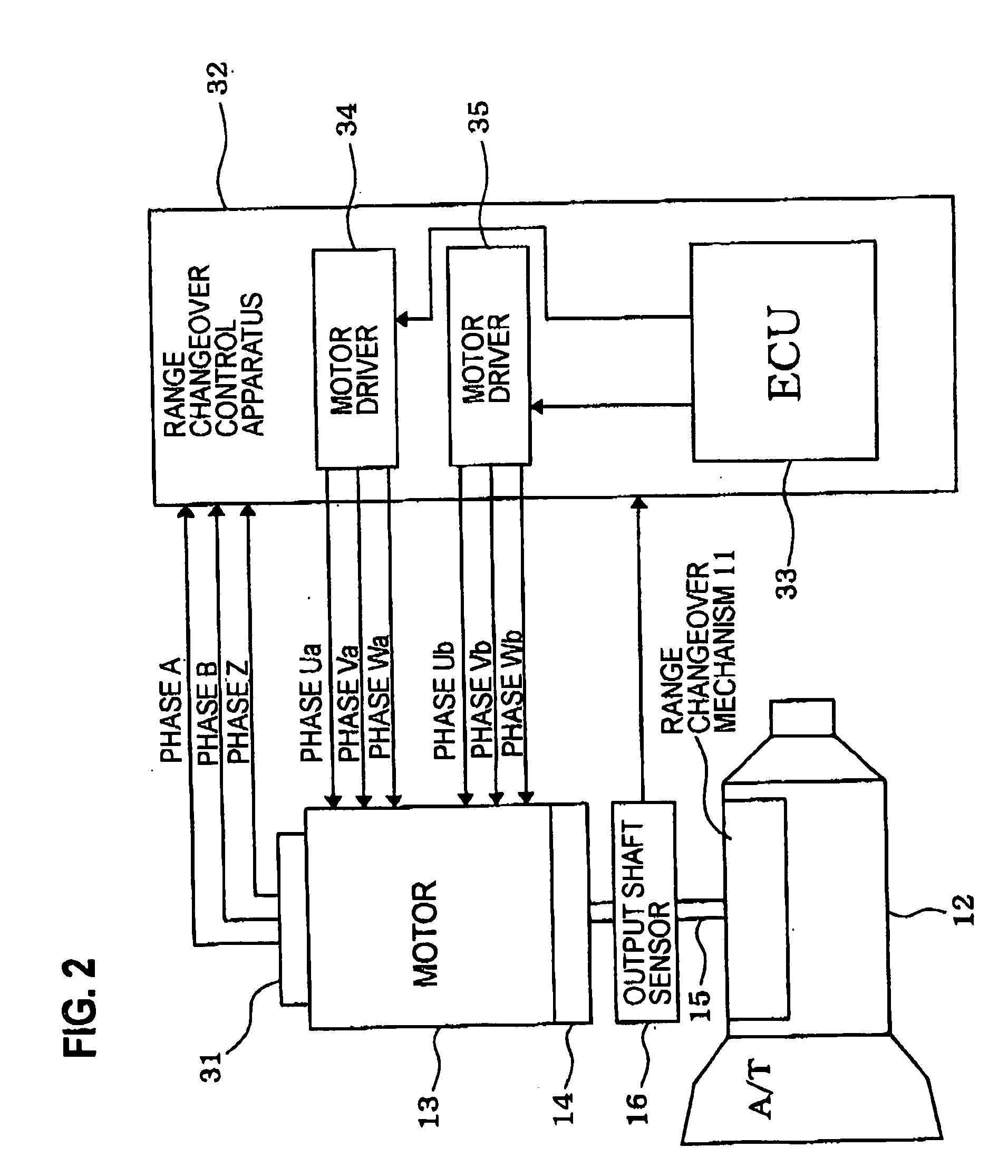
[0065] With the first embodiment, processing is repetitively performed by the ECU 33 at predetermined time intervals whereby the target motor rotation angle θ1tg is set in accordance with the difference amount (θ2−θ2tg), i.e., the deviation of the detected output shaft rotation angle θ2 from the target output shaft rotation angle θ2tg. However immediately after driving of the motor 13 has started, the rotation angle relationship between the output shaft 15 and the motor 13 (i.e., the rotor shaft of the motor 13) is indeterminate, and this condition continues until the motor 13 has rotated by a sufficient amount to take up all of the backlash in the rotation transmission system. As a result, it is not possible to accurately compensate the target motor rotation angle θ1tg by using the detected output shaft rotation angle θ2 from the output shaft sensor 16, during that initial condition after driving of the motor 13 has commenced, until the backlash has been taken up. Thereafter, the o...

third embodiment

[0080] A third embodiment of a motor control apparatus will be described referring to FIGS. 10 to 13. With the first and second embodiments above, the output shaft sensor 16 is formed of a device such as a rotary potentiometer which produces an output voltage that changes linearly in accordance with changes in the angular position of the output shaft 15. With the third embodiment, as shown in FIGS. 10 and 11, the output shaft sensor is configured as a set of four switch sections Psw, Rsw, Nsw, Dsw, respectively corresponding to the P, R, N and D shift positions of the automatic transmission. Each of these switch sections Psw, Rsw, Nsw, Dsw is coupled to the output shaft 15 such as to be set in an ON state, in which an output signal at a level referred to as the ON level is produced, when the output shaft 15 is within a specific corresponding range of angular positions. For each switch section, the corresponding range includes an angular position of the output shaft 15 whereby the co...

fourth embodiment

[0107] With the third embodiment, after driving of the motor 13 has commenced, the second setting of the target motor rotation angle θ1tg is performed only when a first edge of an output signal from one of the switch sections Psw, Rsw, Nsw, Dsw constituting the output shaft sensor is detected. Subsequently, that value of θ1tg is held fixed until completion of the shift position changeover operation. A fourth embodiment will be described, which is basically similar to the third embodiment, employing a map of values for θ1tg such as that of FIG. 13. However the fourth embodiment utilizes a target motor rotation angle setting routine as shown in FIG. 14, in place of the routine of FIG. 12 for the third embodiment. With the fourth embodiment, while the motor 13 is being driven for rotation during a shift position changeover operation, resetting of the target motor rotation angle θ1tg is performed each time a rising edge or falling edge of an output signal from a switch section of the ou...


PUM


Abstract

A motor control apparatus controls a motor that drives an output shaft through a rotation transmission system. The difference between a newly established output shaft target rotation angle and a detected output shaft rotation angle is obtained, a target rotation angle for the motor is derived based on that difference, and the motor is driven accordingly. When it is determined, based on the detected output shaft rotation angle, that motor rotation has at least proceeded to a point whereby backlash in the transmission system is nullified, the target motor rotation angle is updated based on the current value of the aforementioned difference.

Description

CROSS-REFERENCE TO RELATED APPLICATIONS [0001] This application is based on and incorporates herein by reference Japanese Patent Application No. 2004-003758 filed on Jan. 9, 2004. BACKGROUND OF THE INVENTION [0002] 1. Field of Application [0003] The present invention relates to a motor control apparatus for a motor having a rotor shaft that is coupled through a rotation transmission system such as a speed reduction mechanism to an output shaft that drives a control object. [0004] 2. Description of Prior Art [0005] In recent years, there has been an increasing trend in the field of automobile technology towards replacing mechanical systems by systems which are electrically driven, i.e., by electric motors. This is done for reasons such as reduction of the amount of space required, ease of assembly, ease of system control, etc. This is exemplified in Japanese Patent Laid-open No. 2002-323127 (pages 3˜4, etc.), whereby an automatic transmission apparatus (referred to in the following s...

Claims


Application Information

Patent Timeline
Patent Type & Authority Applications(United States)
IPC IPC(8): H02P25/08F16H61/32
CPCF16H2061/326F16H61/32
Inventor NAKAI, YASUHIROKAMIO, SHIGERU
Owner DENSO CORP
Why Eureka
Try Eureka