All fiber autocorrelator

an autocorrelator and fiber technology, applied in the field of all fiber autocorrelators, can solve the problems of reducing the usefulness of such devices, reducing the cost of bulk optic interferometric apparatuses used for accurate, on-line measurement of web and coating layer thickness, and reducing the cost of bulk optics and mechanics. , to achieve the effect of reducing mechanical components, and reducing the cost of bulk opti

Inactive Publication Date: 2005-01-25
HALLIBURTON ENERGY SERVICES INC
View PDF4 Cites 62 Cited by
  • Summary
  • Abstract
  • Description
  • Claims
  • Application Information

AI Technical Summary

Benefits of technology

In the present invention, the disadvantages of the prior art interferometric devices are overcome by eliminating bulk optic and mechanical components, and providing an all fiber device. The mechanical components and open optics are eliminated and instead, scanning is accomplished by means of piezo electric fiber stretchers usually configured in tandem to provide a rapid, accurate measurement with a relatively large dynamic range. Replaceable sensing probes may be any length and do not require length matching to other components of the measuring instrument.

Problems solved by technology

In web and coating manufacturing operations, expensive bulk optic interferometric apparatuses are used for accurate, on-line measurements of web and coating layer thickness.
Unfortunately, the expensive bulk optics and mechanics required in such devices reduce their usefulness except in high value production applications.
In addition, the mechanical nature of the scanning optics of such devices reduce the possible scan rate and service life.

Method used


Image

  • All fiber autocorrelator
  • All fiber autocorrelator
  • All fiber autocorrelator

Examples


Embodiment Construction

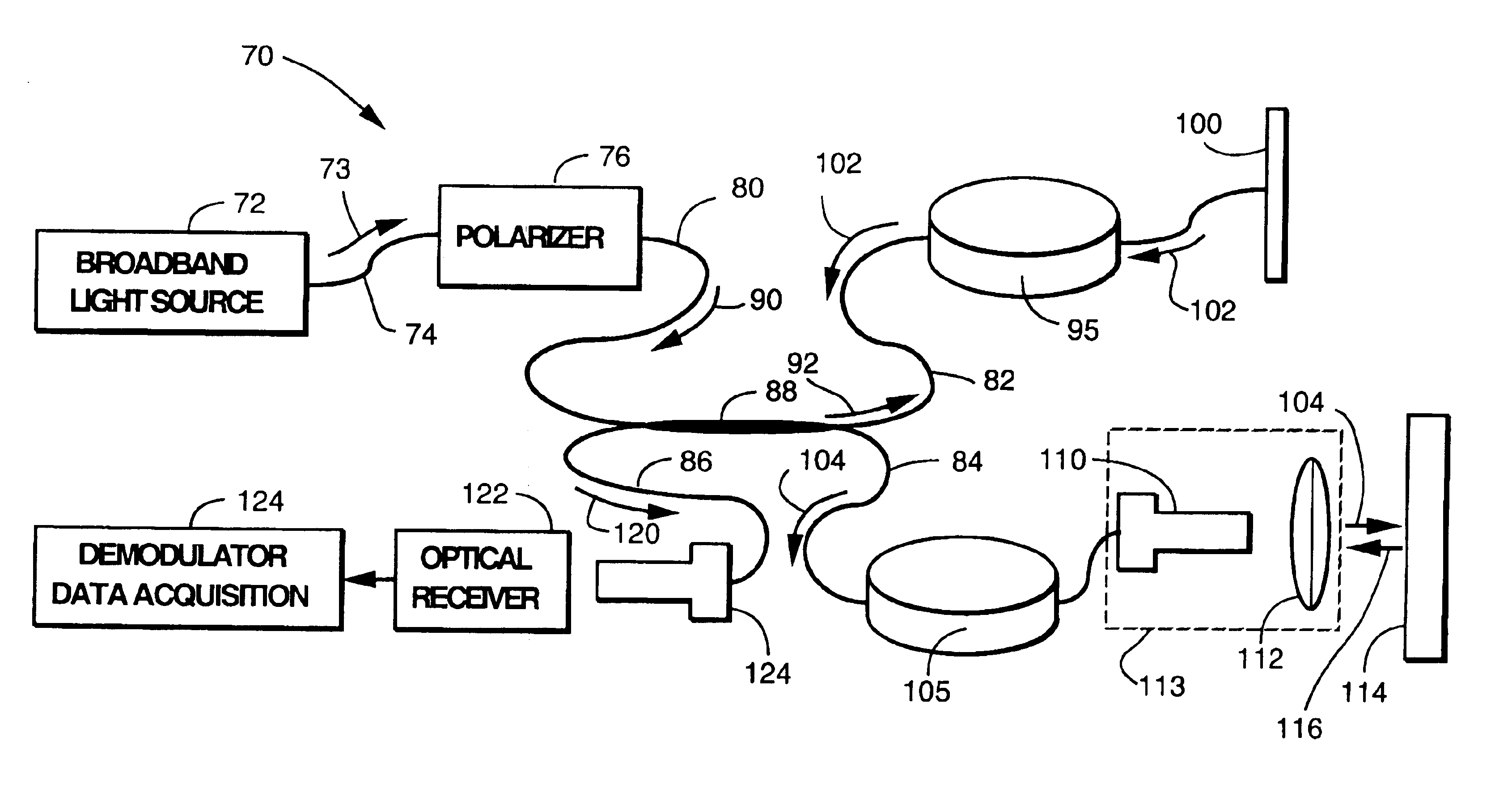
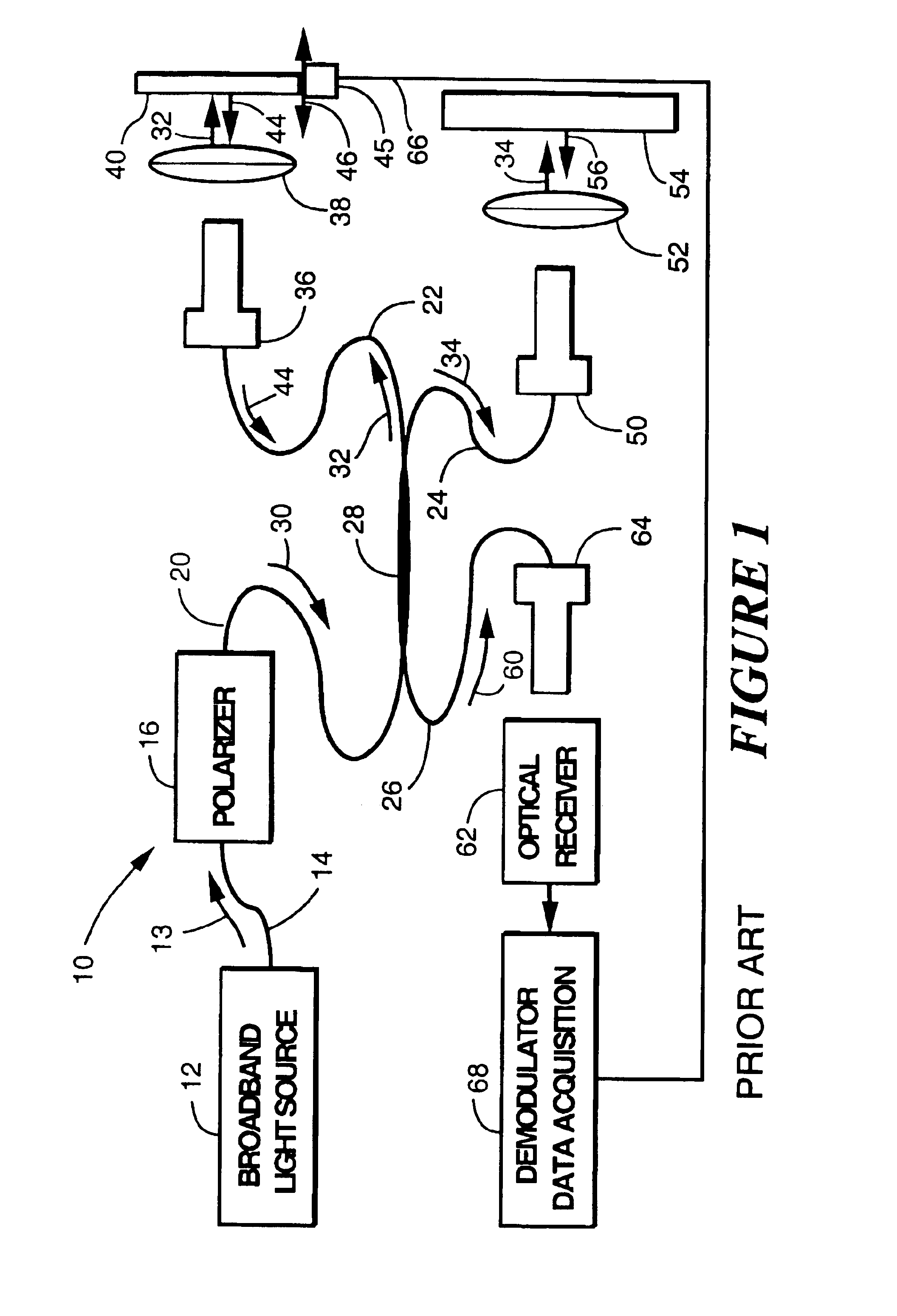
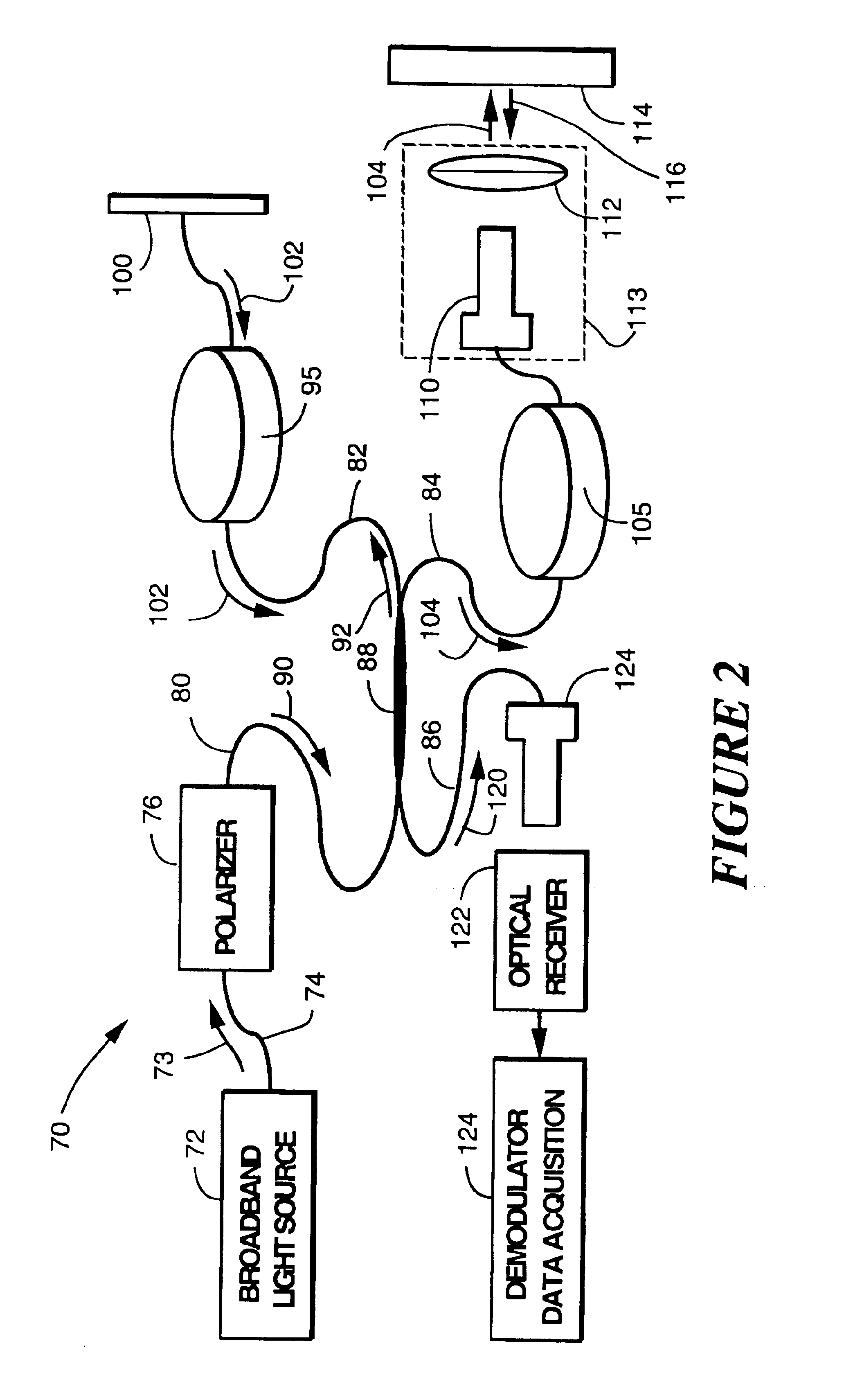
Referring to the drawings more particularly by reference numbers, number 10 in FIG. 1 refers to a prior art Michelson scanning interferometer in which a broadband light source 12 provides white light 13 through a fiber 14 to a polarizer 16. The polarizer 16 and the polarization maintaining fibers 20, 22, 24, and 26 downstream therefrom as well as a polarization maintaining fiber coupler 28 are included to eliminate polarization fading.

The polarized white light 30 passes through the fiber 20 and is split into two light beams 32 and 34 by the polarization maintaining fiber coupler 28. The beam 32 is projected out of a non-reflective fiber termination 36, through a focusing lens 38 and onto a mirror device 40. The mirror device 40 may be a corner cube or retro-reflector to assure that the reflected reference beam 44 returns to the termination 36 without much attenuation. The referenced beam 44 is formed by translating the device 40 typically by means of either a motorized linear slide,...


PUM


Abstract

An autocorrelator apparatus and method for economically measuring physical properties of an object where the measurement path is at least semi-translucent to light, such as thicknesses in multilayered optical structures, group index of refraction, and distance to a surface. The apparatus includes a non-coherent light fiber interferometer and an optional coherent light fiber interferometer in association so as to share PZT fiber modulators. Thickness and boundary extent measurements can be made, for example, of solids, liquids, liquids moving along a horizontal plane, or liquids flowing down a plane.

Description

FIELD OF INVENTIONThe invention relates generally to autocorrelators constructed from optical fiber instead of bulk optics useful for measuring reflection areas in materials and physical properties thereof that are at least semi-transparent to light.BACKGROUND OF THE INVENTIONIn web and coating manufacturing operations, expensive bulk optic interferometric apparatuses are used for accurate, on-line measurements of web and coating layer thickness. An apparatus, such as shown in U.S. Pat. No. 5,633,712, by Venkatesh, et al., U.S. Pat. No. 5,659,392, by Marcus, et al. which issued Aug. 19, 1997 and the associated method taught in U.S. Pat. No. 5,596,409 by Marcus, et al. which issued Jan. 21, 1997 have a high degree of lateral resolution, are light weight, compact, easy to set up, and are robust in high and low temperature environments, in the presence of solvents, high air flow, and various levels of relative humidity. Such apparatuses are self-calibrating or able to remain in calibra...

Claims


Application Information

Patent Timeline
Patent Type & Authority Patents(United States)
IPC IPC(8): G01B11/06G01B9/02
CPCG01B11/0675G01B9/02028G01B9/02007G01B9/0209G01B2290/35G01B2290/70G01B2290/45
Inventor BUSH, IRA JEFFERY
Owner HALLIBURTON ENERGY SERVICES INC
Why Eureka
Try Eureka