Head gimbal assembly
- Summary
- Abstract
- Description
- Claims
- Application Information
AI Technical Summary
Benefits of technology
Problems solved by technology
Method used
Image

Examples
first embodiment
Configuration of First Embodiment
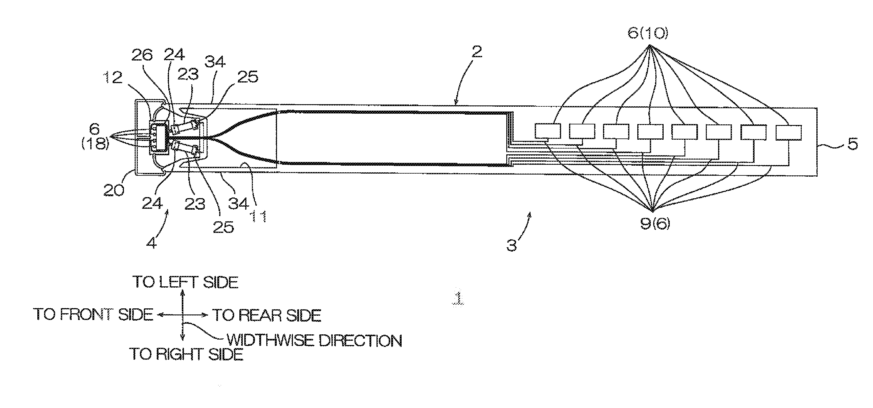
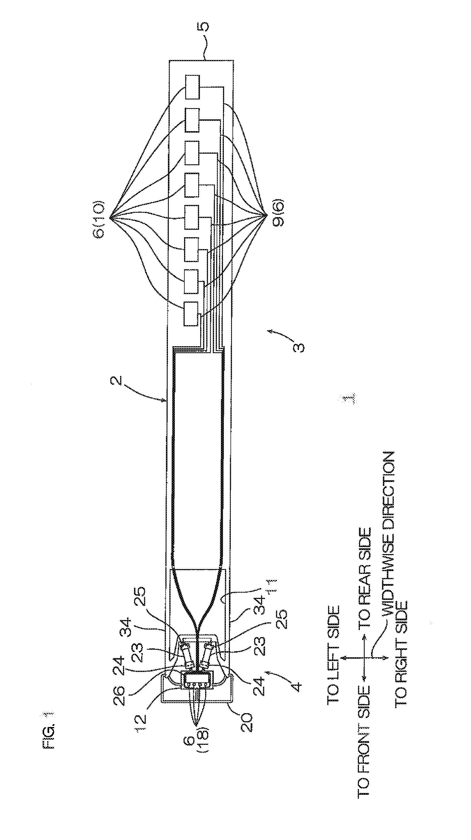
[0030]A head gimbal assembly in a first embodiment of the present invention is described with reference to FIGS. 1 to 4. Note that, in FIG. 1, the left side of the surface of the paper sheet with the drawing is assumed to be a front side (one side in a first direction). The right side of the surface of the paper sheet with the drawing is assumed to be a rear side (the other side in the first direction). The upper side of the surface of the paper sheet with the drawing is assumed to be a left side (one side in a second direction perpendicular to the first direction or one side in a widthwise direction (an example of a crossing direction)). The lower side of the surface of the paper sheet with the drawing is assumed to be a right side (the other side in the second direction or the other side in the widthwise direction). The front side in the thickness direction of the paper sheet with the drawing is assumed to be an upper side (one side in a third dire...
second embodiment
[0078]In FIG. 5 showing a second embodiment, the same members and the same steps as in the first embodiment are designated by the same reference numerals and a detailed description thereof is omitted.
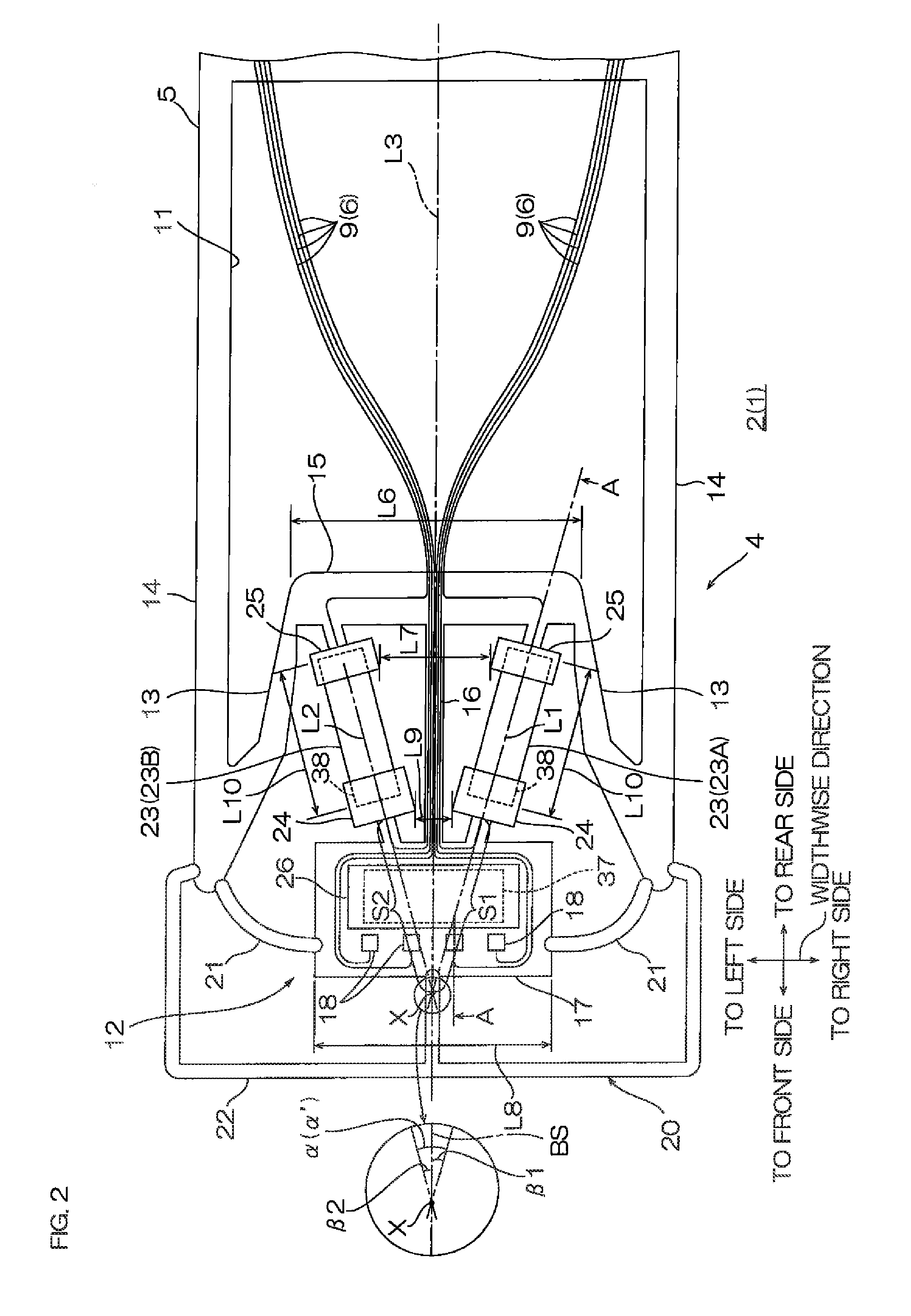
[0079]In the first embodiment, as shown in FIG. 2, the pair of piezo-elements 23 are provided in the head gimbal assembly 1 so as to incline each of the first and second imaginary lines L1 and L2 with respect to the front-rear direction. However, as shown in, e.g., FIG. 5, it is also possible to place only one of the pair of piezo-elements 23, e.g., the right piezo-element 23A such that a line passing through the right piezo-element 23A is gradually inclined widthwise inward (leftward) toward the front side and thus incline only the first imaginary line L1 with respect to the front-rear direction. On the other hand, it is also possible to place the left piezo-element 23B such that a line passing through the left piezo-element 23B extends along the front-rear direction and thus place the...
third embodiment
[0081]In FIGS. 6 and 7 showing a third embodiment, the same members and the same steps as in the first embodiment are designated by the same reference numerals and a detailed description thereof is omitted.
[0082]In the first embodiment, as shown in FIG. 2, the first and second imaginary lines L1 and L2 are inclined so as to be closer to each other toward the slider 26 from the pair of piezo-elements 23. However, as shown in, e.g., FIG. 6, the first and second imaginary lines L1 and L2 can also be inclined so as to grow away from each other toward the slider 26 from the pair of piezo-elements 23.
[0083]Specifically, the first and second imaginary lines L1 and L2 are inclined so as to grow away from each other toward the front side from the point of intersection X. That is, the first and second line segments S1 and S2 form a generally V-shaped shape which is gradually widely open toward the front side from the point of intersection X.
[0084]In the first embodiment, it is possible to all...
PUM
 Abstract
Description
Claims
Application Information