Prioritizing repair of signal leakage in an hfc network

a technology of hybrid fibercoax and signal leakage, applied in the direction of orthogonal multiplex, transmission monitoring, instruments, etc., can solve the problem that the technology that allowed cable network operators to detect and measure leaking qam channels at or near lte frequencies was not available, and cable operators had minimal visibility of these higher frequency leakage problems

Active Publication Date: 2015-06-25
ARCOM DIGITAL
View PDF2 Cites 24 Cited by
  • Summary
  • Abstract
  • Description
  • Claims
  • Application Information

AI Technical Summary

Benefits of technology

[0011]It is still another object of the present invention to provide apparatus and methods of prioritizing the repair of an RE signal leak based on the signal level of a RF forward path signal in the cable network, at or near the leak.
[0012]It is still a further object of the present invention to provide apparatus and methods of prioritizing the repair of an RF signal leak based on leak level, BTS signal level, and the signal level of a RF forward path signal in the cable network at or near the leak.

Problems solved by technology

But, detection of signal leakage in the aeronautical band may have little correlation with signal leakage in the LTE band, and leak mitigation efforts in the aeronautical bands may not have a corresponding benefit in mitigating leaks in the LTE band.
Until recently, technology that allowed cable network operators to detect and measure leaking QAM channels at or near LTE frequencies was not available.
Thus, cable operators had minimal visibility of these higher frequency leaks.
As a result, there are numerous leaks that exist at the LTE band.
Generally, there may be an average of one LTE leak per cable plant mile.
It is unrealistic to attempt to repair all such leaks.
Egress of QAM signals from the cable network can adversely affect the LTE base transceiver station (BTS) performance by raising the BTS receiver noise floor and effectively decreasing the coverage area.
Ingress of LTE signals (from BTS transmitters) entering the cable network through the leak can adversely affect the quality of signal transmission of the QAM channels downstream of the leak.
This is so because it is unlikely that egress from that distant leak location will affect the LTE BTS performance or that the LTE signal ingress will affect the quality of the QAM signals in the network.
Comparing this to a leak of the same amplitude in close proximity to the LTE BTS, where the LTE signal strength is very high, the likelihood of both ingress and egress-related impairments is high.

Method used


Image

  • Prioritizing repair of signal leakage in an hfc network
  • Prioritizing repair of signal leakage in an hfc network
  • Prioritizing repair of signal leakage in an hfc network

Examples


Embodiment Construction

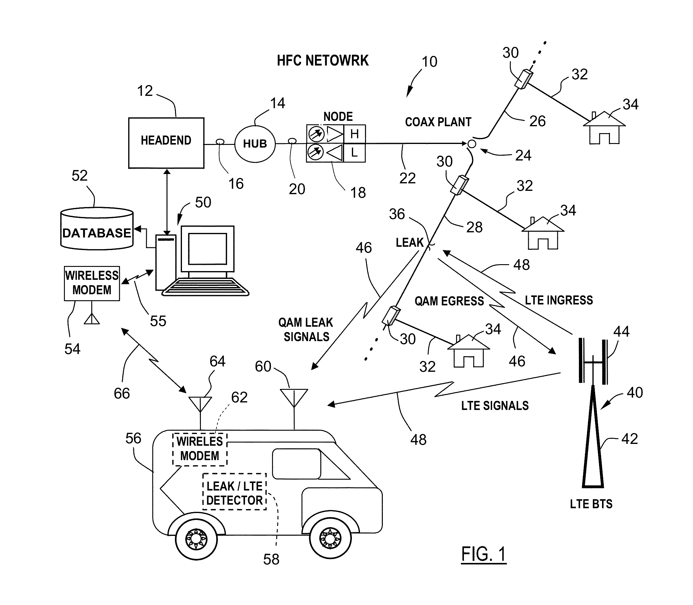
[0033]The QAM Snare® system, manufactured by Arcom Digital, LLC, Syracuse, N.Y., detects and locates QAM leakage in a CATV cable network, utilizing a cross-correlation process and a time-difference of arrival (TDOA) algorithm. The leakage detection process can be summarized as follows. Samples of a QAM channel are captured at a location within the network and time stamped using a Global Positioning System (GPS) reference clock. These samples are treated as a reference and are called “reference samples.” The reference samples are subsequently transmitted over a wired or wireless network to a leakage detector in the field, which is likely installed in a technician vehicle (e.g., the QAM Snare® Monitor™ or Navigator™ leakage detector by Arcom Digital, LLC). The leakage detector similarly uses a GPS reference clock for timing synchronization. The detector receives over-the-air QAM signals leaked from the network, via a locally connected antenna. The detector samples the QAM leakage sign...


PUM


Abstract

A method or apparatus of identifying for repair a signal leak in an HFC network, wherein a base transceiver station in the vicinity of the HFC network transmits a BTS signal over-the-air. The method comprises or apparatus performs the steps of: (a) identifying a location of the signal leak; (b) in the vicinity of the signal leak, detecting the BTS signal; (c) determining a level of the BTS signal; (d) defining a threshold level; (e) with the use of a processor, determining whether the level of the BTS signal meets or exceeds the threshold level; and (f) indicating for repair the signal leak if the level of the BTS signal meets or exceeds the threshold level.

Description

CROSS-REFERENCE TO RELATED APPLICATIONS[0001]This application claims the benefit of U.S. Provisional Application No. 61 / 919,307, filed Dec. 20, 2013.BACKGROUND OF THE INVENTION[0002]1. Field of Invention[0003]The present invention relates generally to detecting, locating and repairing signal leaks in a hybrid fiber-coax (HFC) network, and more particularly to a system and method of prioritizing the repair of such signal leaks.[0004]2. Background Art[0005]The advent of wireless Long Term Evolution (LTE) 4G technology has required the cable television industry to re-evaluate the signal leakage detection processes and to include detection of leaking QAM channel signals at frequencies at or near the LTE band. Since the 1980's, the FCC has defined monitoring requirements and allowable cumulative signal leakage limits for all cable television networks carrying channels in the aeronautical band. As a result of required compliance efforts, as well as good construction, management, and workm...

Claims


Application Information

Patent Timeline
Patent Type & Authority Applications(United States)
IPC IPC(8): H04W24/02H04J11/00G01R31/50
CPCH04J11/0023H04W24/02H04L12/2801H04N21/44209H04N21/6118H04N21/2383H04N21/4382H04L43/045H04L43/0823H04L43/16G01R31/50H04L43/08H04L41/0618H04L41/0609G01R31/002H04B17/318H04B17/345
Inventor ZINEVICH, VICTOR M.
Owner ARCOM DIGITAL
Why Eureka
Try Eureka