
LED driving device

Inactive Publication Date: 2015-06-25
SEOUL SEMICONDUCTOR
View PDF2 Cites 17 Cited by
  • Summary
  • Abstract
  • Description
  • Claims
  • Application Information

AI Technical Summary

Benefits of technology

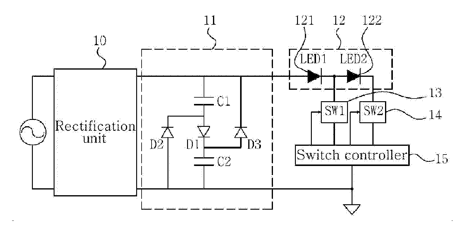
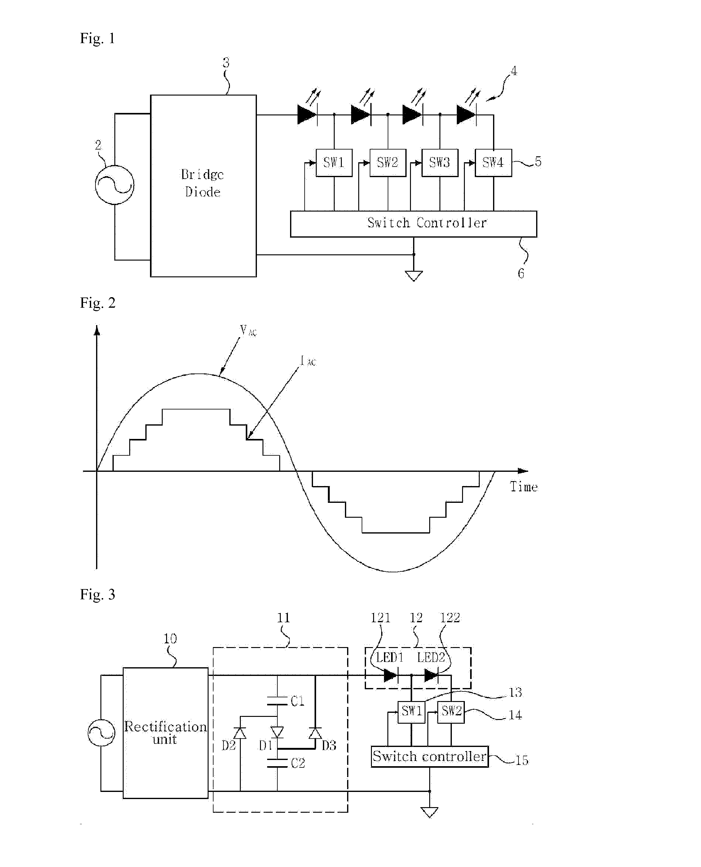
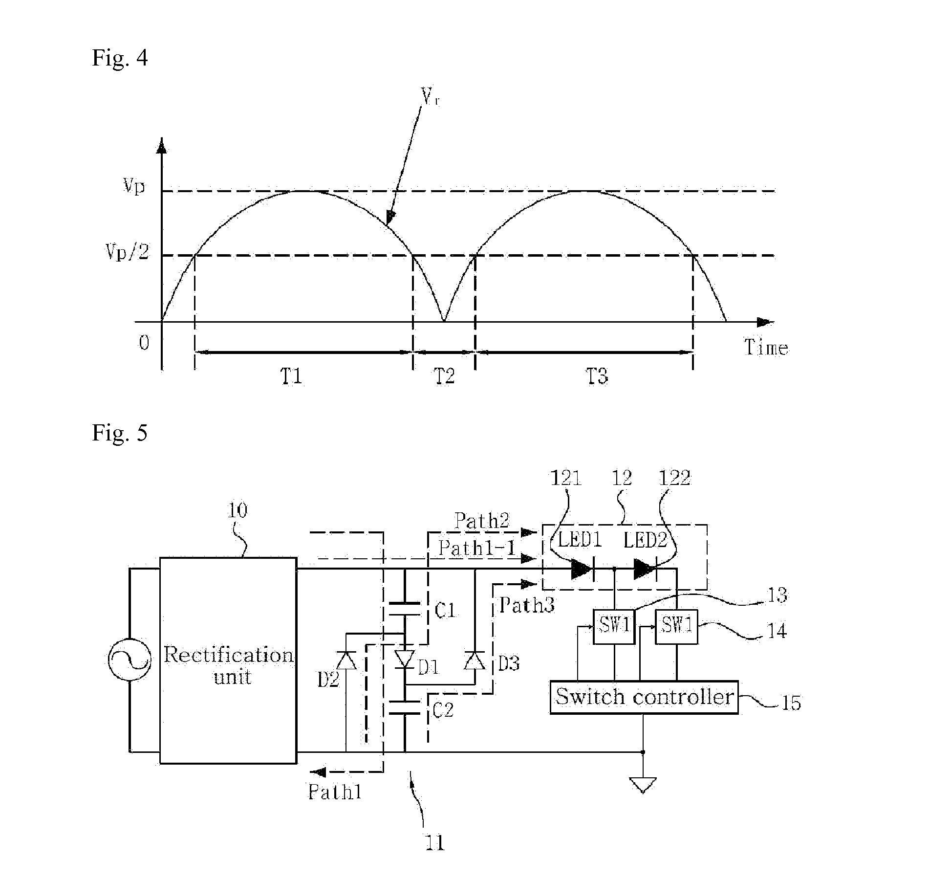
The present invention provides a LED driving device that includes an optical power compensation circuit to improve efficiency and lifespan of an LED array. This eliminates non-light-emitting sections and reduces the size of the apparatus. The unique operational characteristics of the optical power compensation circuit are taken into account to have an effective design in consideration of efficiency of forward voltage of an LED array driven by the multistage current driving circuit. This driving device operates an LED array including a plurality of LED groups to sequentially emit light in response to AC power without using power converting circuits, thereby improving the quality of the light source.

Problems solved by technology

Therefore, the conventional LED driving circuit has a problem that its power factor, total harmonic distortion, and similar electric characteristics do not satisfy standards for products such as LED luminaires (i.e., LED light fixtures).
However, there is a limit to the type or kind of LED groups applicable to such a LED driving device of the multistage current driving mode, and it is difficult to configure the LED driving device and optimal sets of the LED driving device since forward voltage of a LED group selected from the plurality of limited LED groups is already fixed.
That is, in the conventional LED driving device of the multistage current driving mode, adjusting or setting the forward voltage of the plural LED groups in an efficient manner is difficult.
Such a section with no light output (non-light-emitting section) causes light flickering.

Method used


Image

  • LED driving device
  • LED driving device
  • LED driving device

Examples


Embodiment Construction

[0045]In the following description, for the purposes of explanation, numerous specific details are set forth in order to provide a thorough understanding of various exemplary embodiments. It is apparent, however, that various exemplary embodiments may be practiced without these specific details or with one or more equivalent arrangements. In other instances, well-known structures and devices are shown in block diagram form in order to avoid unnecessarily obscuring various exemplary embodiments.

[0046]Terms and words used in the following description and claims should be interpreted as having a meaning that is consistent with their meaning in the context of the specification and relevant art and should not be interpreted in an idealized or overly formal sense as defined in commonly used dictionaries. In addition, the disclosure in the specification and the configurations shown in the drawings are just exemplary embodiments of the present invention and do not cover all the technical id...


PUM


Abstract

Disclosed is an LED driving apparatus capable of removing a non-light-emitting section and extending device life span by adding an optical power compensation circuit to a driving circuit of a multi-stage current driving mode. The design is more efficient with respect to a forward voltage of an LED array driven by the multi-stage current driving circuit and the unique operational characteristics of the optical power compensation circuit. The LED driving apparatus drives a plurality of LED groups and includes a rectification unit for rectifying an AC voltage to generate a ripple voltage at an output, an optical power compensation unit to supply a pre-stored compensation voltage to the LED array when the ripple voltage is less than a minimum forward voltage in the plurality of LED groups, and a constant current driving unit connected the plurality of LED groups to sequentially drive each LED group with a constant current.

Description

[0001]This application is the National Stage Entry of International Application PCT / KR2012 / 010948, filed on Dec. 14, 2012, and claims priority from and the benefit of Korean Patent Application No. 10-2011-0136740, filed Dec. 16, 2011 and Korean Patent Application No. 10-2012-0146675, filed Dec. 14, 2012, all of which are incorporated herein by reference for all purposes as if fully set forth herein.BACKGROUND[0002]1. Field[0003]The present invention relates to a light emitting diode (LED) driving device, and more particularly, to an LED driving device in which an optical power compensation circuit is added to a multistage current driving circuit and unique operational characteristics of the optical power compensation circuit are taken into account to have an effective design in consideration of efficiency of forward voltage of an LED array driven by the multistage current driving circuit, thereby removing a non-light-emitting section and extending the lifespan of an apparatus.[0004]...

Claims


Application Information

Patent Timeline
IPC IPC(8): H05B33/08H05B44/00
CPCH05B33/083H05B33/0845H05B33/0809H05B45/44H05B45/48H05B45/3725H05B45/37
Inventor KANG, HYUN GUJUNG, HYE MAN
Owner SEOUL SEMICONDUCTOR
Learn More