Ultrasonic motor

a technology of ultrasonic motors and supports, applied in the field of motors, can solve the problems of incorrect control of the position of the rail, and achieve the effect of improving the feeding accuracy of the vibrator support member

Active Publication Date: 2015-07-02
CANON KK
View PDF0 Cites 20 Cited by
  • Summary
  • Abstract
  • Description
  • Claims
  • Application Information

AI Technical Summary

Benefits of technology

[0008]According to the present invention, the base to which the vibrator is fixed and the vibrator support member are relatively held with a flexibility in the pressurizing direction and without any rattle in a moving direction, to hold the vibrator without causing any rattle in the moving direction, so that a feeding accuracy of the vibrator support member can be improved.

Problems solved by technology

Therefore, for example, when an impact force is applied due to vibration, dropdown or the like, relative positions of the fixing plate and a vibrating plate disadvantageously deviate, which causes the problem that a position of the rail 11a cannot correctly be controlled.

Method used


Image

  • Ultrasonic motor
  • Ultrasonic motor
  • Ultrasonic motor

Examples


Embodiment Construction

[0013]Preferred embodiments of the present invention will now be described in detail in accordance with the accompanying drawings. In the drawings, the same part is denoted with the same symbol.

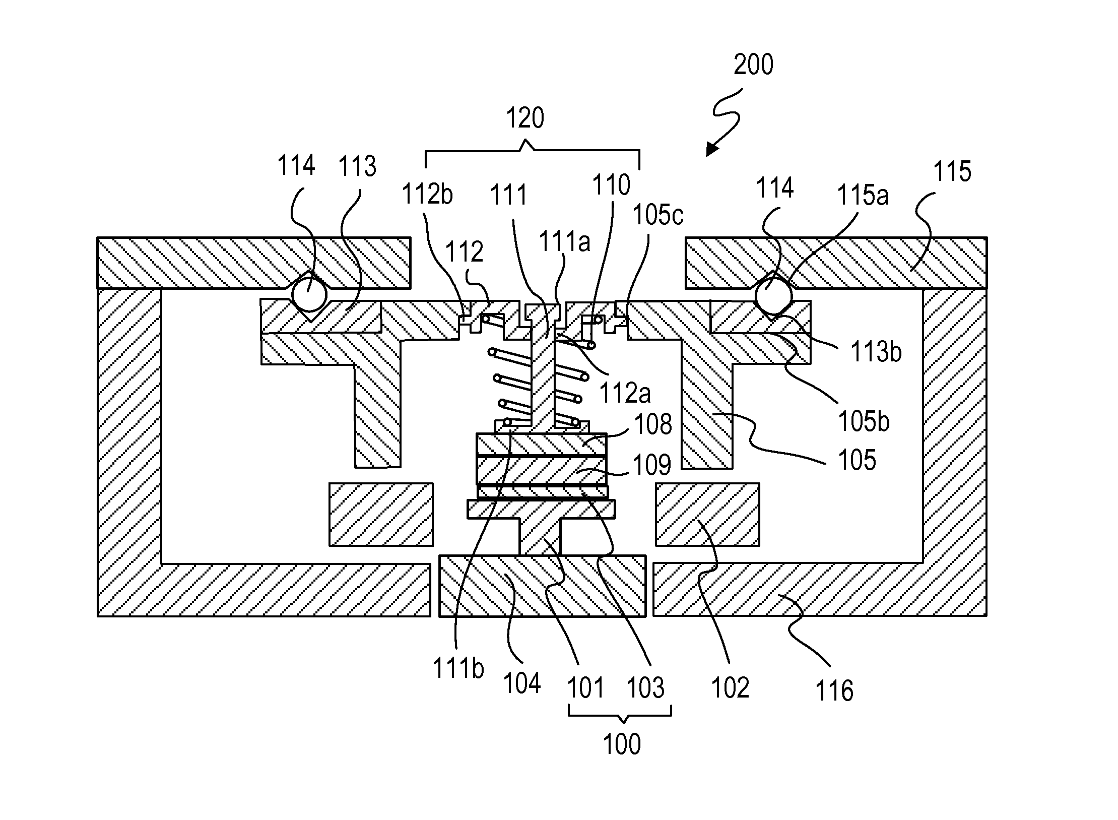
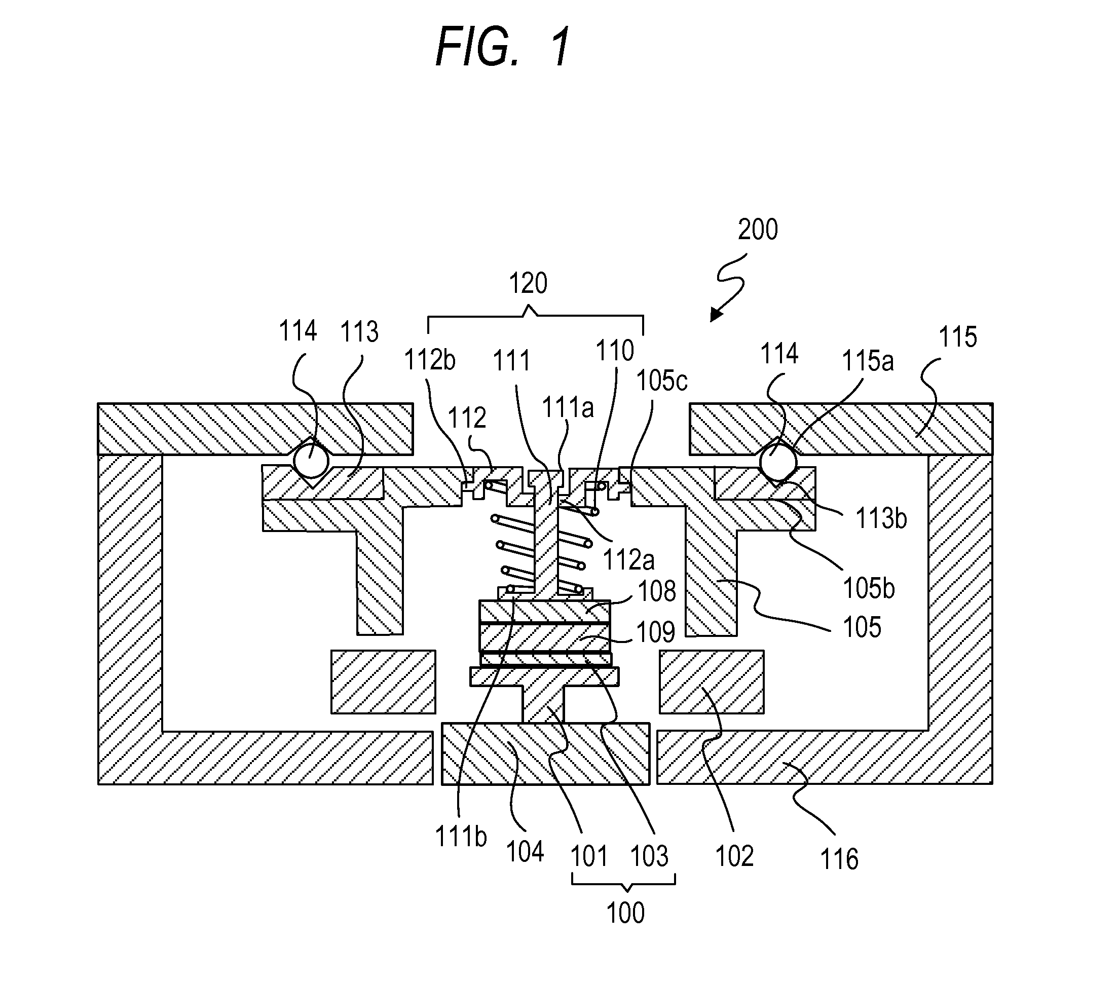
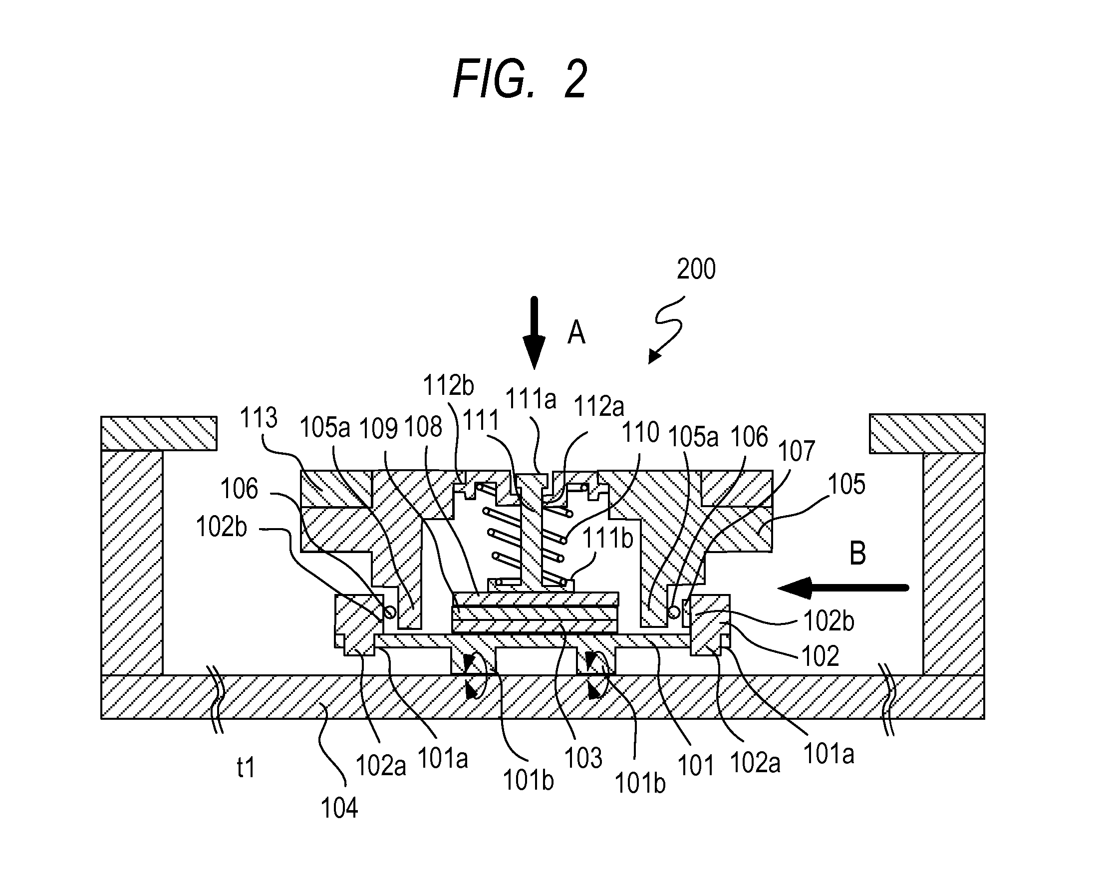
[0014]FIG. 1 is a sectional view of a main part of an ultrasonic motor showing an embodiment of the present invention (showing a perpendicular cross section in a drive direction), and FIG. 2 is a sectional view of the main part of the ultrasonic motor showing the embodiment of the present invention in a moving direction. Furthermore, the present embodiment will be described on the basis of a direct acting type (linear type) of ultrasonic motor as an example, but the present embodiment is also applicable to another type such as a rotary type.

[0015]An ultrasonic motor 200 includes a vibrating plate 101. The vibrating plate 101 includes portions 101a to be joined. The portions 101a to be joined are fixed to joining convex portions 102a of a base 102 by bonding or the like (see FIG. 2). The base ...


PUM


Abstract

There is disclosed an ultrasonic motor having a vibrator that vibrates by a high frequency drive voltage applied thereto, a sliding member that comes in contact frictionally with the vibrator, pressurizing means for pressurizing the vibrator to the sliding member, a base to which the vibrator is fixed, a vibrator support member holding the base, and coupling means for coupling the vibrator with the vibrator support member, the vibrator and the sliding member being relatively moved by the vibration, wherein the coupling means includes the base, the rolling member that freely moves the base to the vibrator support member in a pressurizing direction of the pressurizing means, and an urging member that urges the rolling member in a direction perpendicular to the pressurizing direction of the pressurizing means.

Description

BACKGROUND OF THE INVENTION[0001]1. Field of the Invention[0002]The present invention relates to a motor which is applied to an optical device or the like. More particularly, it relates to an ultrasonic motor which is applied to the optical device or the like.[0003]2. Description of the Related Art[0004]Heretofore, in this type of ultrasonic motor, a vibrator that periodically vibrates by application of a high frequency voltage is brought into contact under pressure with a sliding member to drive the sliding member.[0005]However, in a related art described in Japanese Patent Application Laid-open No. 2001-292584, one spring member 17 and a plurality of rubber sheets 15, 16 and 18 are provided with a function of supporting a vibration node portion of a vibrating body 14 (corresponding to a vibrator of the present invention) and a function of pressurizing the vibrating body to generate a friction force between the vibrating body and a rail 11a (corresponding to a sliding member of the...

Claims


Application Information

Patent Timeline
Patent Type & Authority Applications(United States)
IPC IPC(8): B06B1/06H01L41/053
CPCH01L41/0536B06B1/0644H02N2/0055H02N2/026G02B7/08H10N30/886
Inventor YAMAMOTO, HARUSHIGE
Owner CANON KK
Why Eureka
Try Eureka