Torsional Suspensioned, Steerable, Oscillating and Propelling Axle Assembly

a technology of rotating suspension and propelling axle, which is applied in the direction of steering parts, non-deflectable wheel steering, vehicle components, etc., can solve the problems of increasing component weight, affecting operator and occupant ride quality and comfort, and affecting the fraction and propulsion negatively, so as to reduce ground pressure and disturbance, improve the travel speed, and reduce the effect of ground pressure and disturban

Active Publication Date: 2015-07-02
MANNERING SHANE G
View PDF17 Cites 7 Cited by
  • Summary
  • Abstract
  • Description
  • Claims
  • Application Information

AI Technical Summary

Benefits of technology

[0030]One advantage of the invention, being extremely robust and less complex than all-terrain vehicles or machines utilizing a-arm suspensions, the invention enables the use of much larger tracks which significantly decrease ground pressure and disturbance resulting in superior over snow and soft underfoot soil condition travel.
[0031]Another advantage of the invention is that the majority of components that make up the invention are typically common, readily available and very economical, whereas the components of other past and current tracked all-terrain vehicles and machines are unique to said vehicles or machines resulting in limited availability with very high repair or replacement cost.
[0032]Yet another advantage is that the invention allows each individual track unit to oscillate over varying, adverse and rough terrain.
[0033]All-terrain vehicles and machines utilizing this invention achieve considerably better traction, less impact and shock loads on said all-terrain vehicle and machine components, with significant improvement in operator / occupant ride quality and comfort.
[0034]Still another advantage of this invention is that it can be used for both the front and rear track units of the all-terrain vehicle or machine thus providing steering both front and rear, allowing for smoother and tighter turns, whereas a-arm equipped vehicles or machines typically have only front steering.
[0035]Since this invention provides and enables the suspension, steering, oscillation and propelling of the track units individually, overall stresses against the main structures such as the frames and cabs of the all-terrain vehicle or machine is considerably less than on past and current vehicles or machines that utilize tilting, rotating turntables with leaf sprung solid axles or machines utilizing fore and aft articulating frame assemblies.

Problems solved by technology

Leaf sprung automotive axle configurations do not allow for true independent suspension as the automotive axle is one complete housing where should one side of the axle rise or fall due to variances in terrain, the other side of the axle would also be effected by this movement opposingly rising or falling, negatively effecting fraction and propulsion, also negatively effecting operator and occupant ride quality and comfort.
This suspension, steering configuration has many component wear points, increased component weight, lacks severely in overall durability and being that many of the components are unique to the vehicle, component maintenance, repair or replacement cost is extremely high.
This type of four track machine typically has little or no suspension, very high frame and undercarriage stress, decreased ride quality and comfort and again very high component wear, weight, repair or replacement cost.
These suspensions work well for tire / wheel applications where leverage stresses are low but with the extended force and leverage that a track unit can exert on A-arm suspensions, life expectancy of these components is significantly reduced and component wear, repair or replacement cost is significantly higher.
Because A-arm suspensions lack in durability from the increased leverage of a track unit, the size of track used has to be significantly decreased which increases ground pressure and reduces the ability of said vehicles or machines to travel over snow or in soft underfoot soil conditions.
Some past and current two track machines utilize torsion axles for individual idler or load wheel suspension but are not in direct assembly with steering, oscillation or propelling functions.
Also past and current two track machines do not have the ability to oscillate the track units and typically will “porpoise” over rough and adverse terrain creating high stresses on the overall vehicle, loss of traction and discomfort for operators and occupants.
Because steering, suspension and propelling on the prior mentioned designs are achieved separately, these designs increase the amount of components needed thereby adding considerable weight to the machine, increasing the machine ground pressure therefore decreasing the machine's ability to travel over snow or in soft underfoot soil conditions.
With the increased amount of components comes increased weight, component wear, repair or replacement cost.
Again with the many unique components of prior mentioned designs, limited availability and increased cost of said components is also common.
Because of erratic movements and at times the complete stopping of one track, resultant of the two tracked vehicle's steering configuration, said vehicles typically will dig themselves down into the snow or soft underfoot soil while turning, often resulting in the vehicle becoming stuck and unable to travel.

Method used


Image

  • Torsional Suspensioned, Steerable, Oscillating and Propelling Axle Assembly
  • Torsional Suspensioned, Steerable, Oscillating and Propelling Axle Assembly
  • Torsional Suspensioned, Steerable, Oscillating and Propelling Axle Assembly

Examples


Embodiment Construction

[0041]The following use of, or reference to, “invention” and / or “axle assembly”, pertains directly to the “Torsional Suspensioned, Steerable, Oscillating and Propelling Axle Assembly.

[0042]It is to be understood that the following details of construction and the arrangement of components in no way limit the scope of the invention. Those skilled in the art will appreciate that other aspects, objects, and advantages of the invention can be obtained from a study of the detailed description, drawings and claims. It is also to be understood that the phraseology and terminology used herein, is for the purpose of description and should not be regarded as limiting.

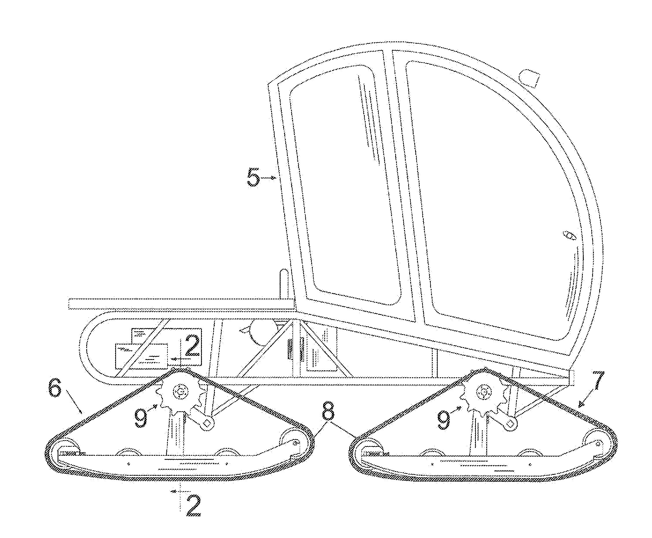
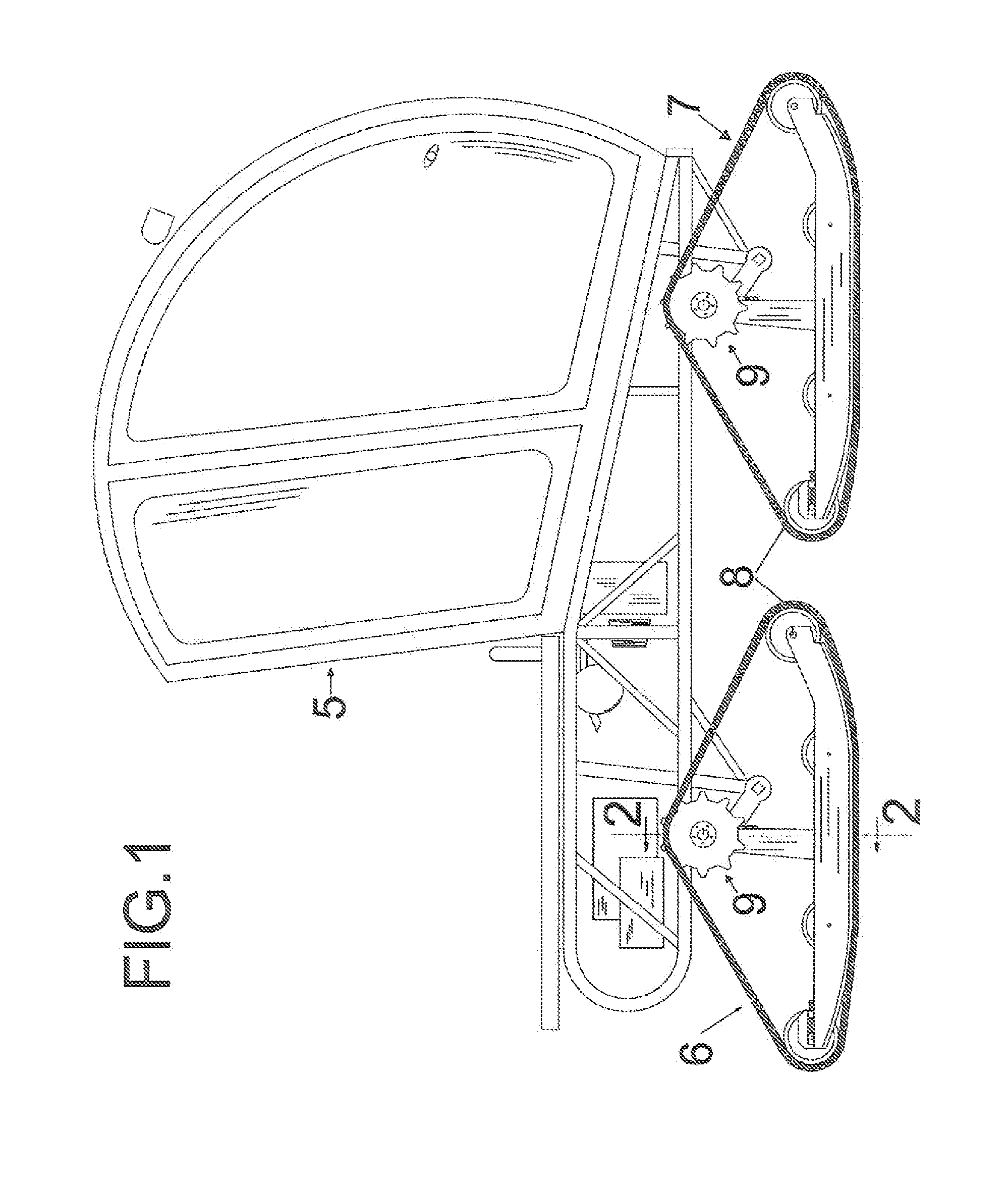
[0043]Referring to FIG. 1 illustrating a side view of four tracked, all-terrain vehicle 5. All-terrain vehicle 5 is typically, but not limited to use in snow, soft underfoot soil and / or adverse terrain conditions. All-terrain vehicle 5 is supported by four individual track units, similarly configured to an automotive wheeled confi...


PUM


Abstract

A “Torsional Suspensioned, Steerable, Oscillating and Propelling Axle Assembly” utilized in the individual track units of a multi track unit all-terrain vehicle or machine with said axle assemblies providing/enabling suspension, steering, oscillation and propelling functions of the track units of the all-terrain vehicle or machine.

Description

CROSS REFERENCE TO RELATED APPLICATIONS[0001]The present Non-Provisional patent application claims the benefits of priority of U.S. Provisional Patent application 61 / 964,255 entitled “Torsional Suspensioned, Steerable, Oscillating, and Propelling Axle Assembly”. Confirmation #3920 Provisional Patent filing date: Dec. 30, 2013STATEMENT REGARDING FEDERALLY SPONSORED RESEARCH OR DEVELOPMENT[0002]Not applicableREFERENCE TO SEQUENCE LISTING, A TABLE, OR A COMPUTER PROGRAM LISTING COMPACT DISC APPENDIX[0003]Not applicableBACKGROUND OF THE INVENTIONField of Endeavor[0004]The present invention relates to all-terrain tracked vehicles or machines and more particularly to providing / enabling the suspension, steering, oscillating and propelling functions of said all-terrain vehicles or machines.[0005]All-terrain vehicles or machines used for over snow travel or on soft underfoot soil conditions utilizing tracks either endless or spliced are commonly of the four or two track configuration.[0006]A...

Claims


Application Information

Patent Timeline
Patent Type & Authority Applications(United States)
IPC IPC(8): B62D11/20B62D55/108B62D55/065
CPCB62D11/20B62D55/065B62D55/1083B62D7/1509B62D55/12B62D55/15B62D55/10B62D55/08B62D55/084B62D55/104B62D55/108
Inventor MANNERING, SHANE
Owner MANNERING SHANE G
Why Eureka
Try Eureka