Rich-Lean Burner

a burner and rich-lean technology, applied in the direction of burners, combustion types, combustion processes, etc., can solve the problems of reducing the cost of making the entire burner main body of expensive sus-based materials, and limiting the temperature of the burner, so as to reduce the thermal effect of the flames generated at the lean flame port onto the bridge portions, the effect of preventing the deterioration of combustibility

Inactive Publication Date: 2015-07-02
RINNAI CORP
View PDF6 Cites 20 Cited by
  • Summary
  • Abstract
  • Description
  • Claims
  • Application Information

AI Technical Summary

Benefits of technology

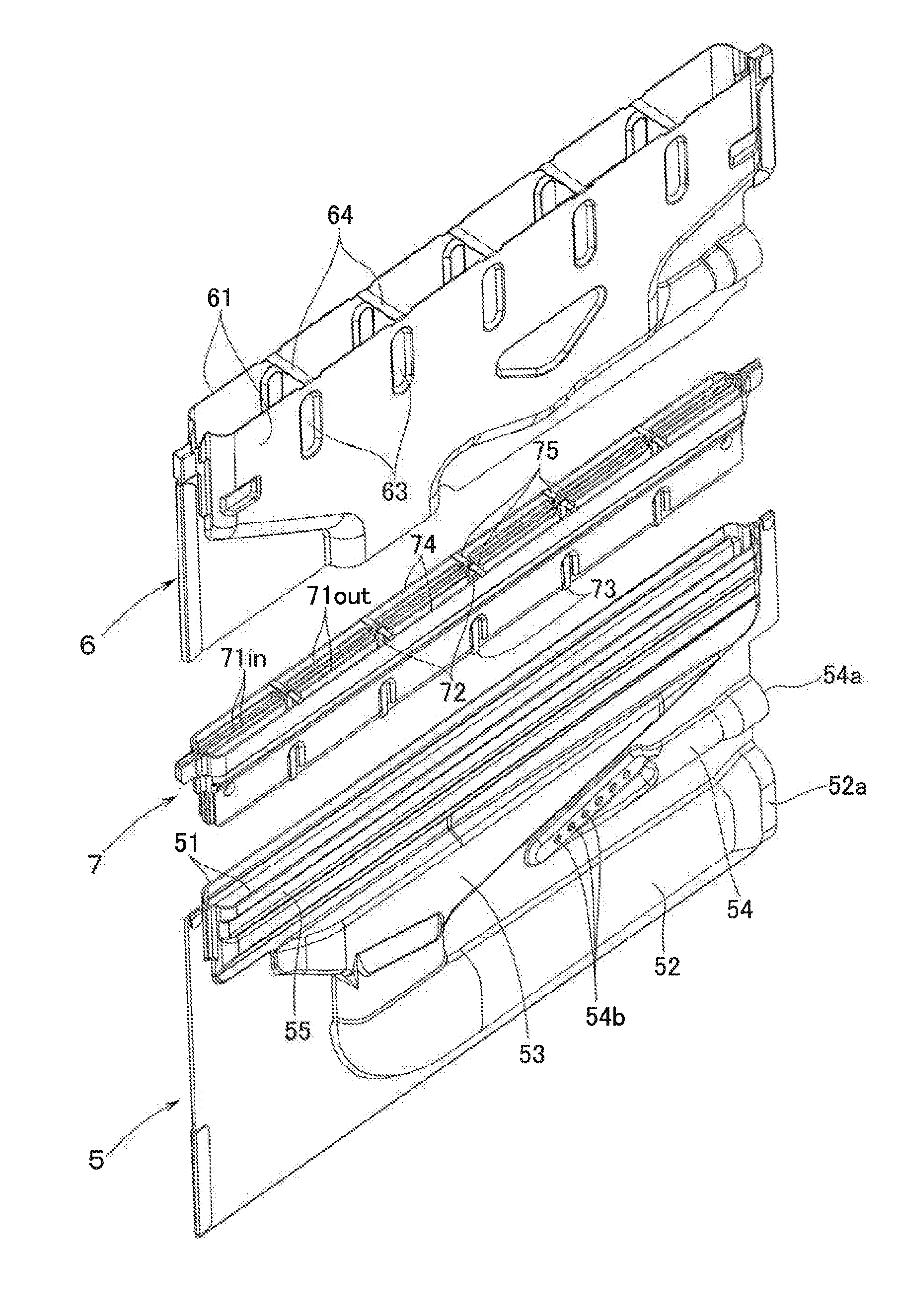
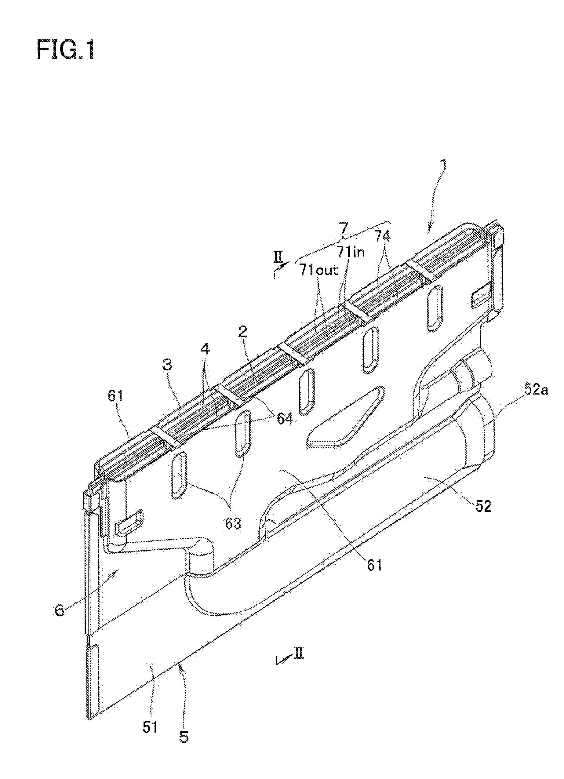
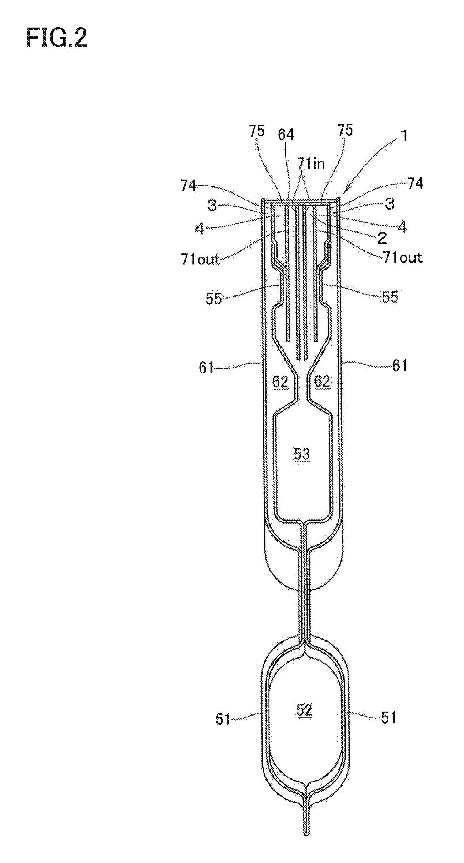
[0009]The straightening member preferably further comprises straightening-member bridge portions arranged at a plurality of longitudinally separate positions, each of the bridge portions connecting an upper end of the partition plate and an upper end of the outer straightening plate. According to this arrangement, the straightening-member bridge portions serve the purpose of a support so that the lateral positional deviation of the partition plates due to aged deterioration can be restricted. Therefore, there can be effectively prevented the deterioration in combustibility as a consequence of lateral changes in the widths of the rich flame port and the blind clearance due to lateral deviation of the partition plate.
[0010]The straightening member preferably further comprises constricted (or gathered) portions at longitudinally separated positions that coincide with each of the bridge portions. The constricted portions are arranged by laterally bringing the plurality of straightening plates into intimate contact with one another, thereby longitudinally dividing the lean flame port. According to this arrangement, the thermal effect by the flames to be generated at the lean flame port onto the bridge portions can be reduced, whereby the durability of the bridge portions is improved.
[0011]The burner cap preferably comprises: a pair of side plates to cover the burner main body from an outside of laterally one side and from an outside of laterally opposite side; and burner-cap bridge portions disposed at a plurality of longitudinal positions to connect upper ends of both the side plates. Each of the burner-cap bridge portions is disposed at longitudinal positions coinciding with each of the straightening-member bridge portions in contact with a top of each of the straightening-member bridge portions. According to this arrangement, the burner-cap bridge portion is cooled as a result of heat sink to the straightening-member bridge portions which are maintained at a relatively low temperature. As a result, the durability of the burner-cap bridge portions can be improved.

Problems solved by technology

However, that portion of the burner main body which is subjected to a high temperature is limited to an upper end of the side plate.
Therefore, it will be a problem in cost reduction to make the entire burner main body of an expensive SUS-based material.

Method used


Image

  • Rich-Lean Burner
  • Rich-Lean Burner
  • Rich-Lean Burner

Examples


second embodiment

[0031]In a second embodiment as shown in FIG. 5, the bridge portion 75 which connects the upper end of each of the partition plates 74 and the upper end of each of the outer straightening plates 7 lout is not provided. Instead, there may be employed an arrangement in which each of the outer straightening plates 71out and each of the partition plates 74 are connected together at folded connecting portions 76 which are provided at a plurality of longitudinal lower end positions.

third embodiment

[0032]Furthermore, in a third embodiment as shown in FIG. 6, the following arrangement is employed in which the side plate 61 on laterally one side (right side as seen in FIG. 6) of the burner cap 6 is overlapped with the partition plate 74 on the right side of the straightening member 7, whereby the right-side rich flame port 3 may be eliminated. In this case, a similar rich-lean burner 1 is provided on the right side thereof in parallel with each other. And the rich flame port 3 on the left side of the latter (right-side) rich-lean burner 1 is arranged to be in close contact with the blind clearance 4 on the right side of the former (left-side as seen in FIG. 6) rich-lean burner 1.

fourth embodiment

[0033]Still furthermore, as shown in FIG. 7, it is possible to eliminate not only the rich flame port 3 on the laterally one side (right side as seen in FIG. 7), but also the right-side blind clearance 4, the side plate 61 on the right side of the burner cap 6, and the partition plate 74 on the right side of the straightening member 7. In this case, a similar rich-lean burner 1 is disposed on the right side of the rich-lean burner 1 in parallel with each other. Between the outer straightening plate 71out on the right side of the straightening member 7 of the former rich-lean burner 1, and the side plate 61 on the left side of the burner cap 6 of the latter rich-lean burner 1, there is defined a blind clearance 4′ which is located between the lean flame port 2 of the former rich-lean burner 1 and the rich flame port 3 of the latter rich-lean burner 1.


PUM


Abstract

A rich-lean burner with a lean flame port, a blind clearance, and a rich flame port has: a burner main body with a pair of burner-main-body side plates on both lateral sides thereof; a burner cap with a burner-cap side plate covering the burner main body from at least one lateral outside thereof; and a straightening member with straightening plates to divide the lean flame port into laterally disposed zones. Upper ends of the burner-main-body side plates are below upper ends of the burner-cap side plate and of the straightening plates. The straightening member has a partition plate which is located laterally outside an outer straightening plate contiguous to the blind clearance and which extends upward beyond the burner-main-body side plates. The blind clearance is defined between the partition plate and the outer straightening plate, and the rich flame port is defined between the partition plate and the burner-cap side plate.

Description

BACKGROUND OF THE INVENTION[0001]1. Technical Field[0002]The present invention relates to a rich-lean burner having on an upper end portion thereof a lean flame port which is extended in a back-and-forth direction (hereinafter referred to as a “longitudinal” direction) in order to eject a lean fuel / air mixture which is leaner in fuel concentration than a theoretical fuel / air ratio; a blind clearance which is located on at least one right-and-left side (hereinafter referred to as a “lateral” side) of the lean flame port and which is free from ejection of a fuel / air mixture; and a rich flame port which is located on a lateral outside of the blind clearance so as to eject a rich fuel / air mixture which is richer in fuel concentration than the theoretical fuel / air ratio.[0003]2. Background Art[0004]As this kind of rich-lean burner, there is known one having as its constitutional elements: a burner main body including a pair of side plates laterally lying opposite to each other; a burner ...

Claims


Application Information

Patent Timeline
Patent Type & Authority Applications(United States)
IPC IPC(8): F23D14/04F23D14/58F23D14/08F23D14/46
CPCF23D14/045F23D14/46F23D2205/00F23D14/08F23D14/586F23D14/105
Inventor AKAGI, KAZUYUKIOKAMOTO, HIDEO
Owner RINNAI CORP
Why Eureka
Try Eureka