Organic light emitting display and pixel compensation circuit and method for organic light emitting display

a technology of pixel compensation circuit, which is applied in the direction of instruments, static indicating devices, etc., can solve the problems of ineffective pixel compensation, inability to accurately compensate for subsequent thresholds, and uneven brightness of the whole organic light emitting display, so as to reduce the impact of parasitic capacitance coupling effect on potential and good display

Active Publication Date: 2015-07-02
SHANGHAI TIANMA MICRO ELECTRONICS CO LTD +1
View PDF6 Cites 18 Cited by
  • Summary
  • Abstract
  • Description
  • Claims
  • Application Information

AI Technical Summary

Benefits of technology

[0010]In view of this, embodiments of the present invention provide a pixel compensation circuit and method for an organic light emitting display to solve the technical problem of the low precision of the pixel compensation for the organic light emitting display, to implement accurate compensation for the threshold voltage.
[0017]The present invention reduces the impact of an parasitic capacitance coupling effect on the potential at a node and solves the problem of inaccurate threshold detecting, by ensuring that voltages at both ends of a storage capacitor do not change simultaneously in the process of compensating the threshold voltage and the power supply line voltage drop, therefore, the threshold voltage is precisely compensated to achieve a good displaying effect.

Problems solved by technology

Specifically, a drift in the threshold voltage of a thin film transistor may cause an uneven brightness of the whole organic light emitting display.
As a result, in the period of detecting the threshold voltage of the thin film transistor T1, the detected threshold voltage Vth′ is inaccurate and is different from the actual threshold voltage Vth by ΔVth, which leads to the inaccuracy of subsequent threshold compensation.
It can be seen from the above equation the pixel compensation is ineffective because of the presence of the ΔVth, and the organic light emitting display still has the problem of uneven brightness.

Method used


Image

  • Organic light emitting display and pixel compensation circuit and method for organic light emitting display
  • Organic light emitting display and pixel compensation circuit and method for organic light emitting display
  • Organic light emitting display and pixel compensation circuit and method for organic light emitting display

Examples


Embodiment Construction

[0027]Technical solutions of the present invention will be described below in conjunction with accompanying drawings and with reference to specific embodiments. It is to be understood that the specific embodiments described herein are only illustrative of the invention but not to limit the present invention herein. It should be additionally noted that, for ease of description, only relevant parts but not all parts of the present invention are shown in the accompanying drawings.

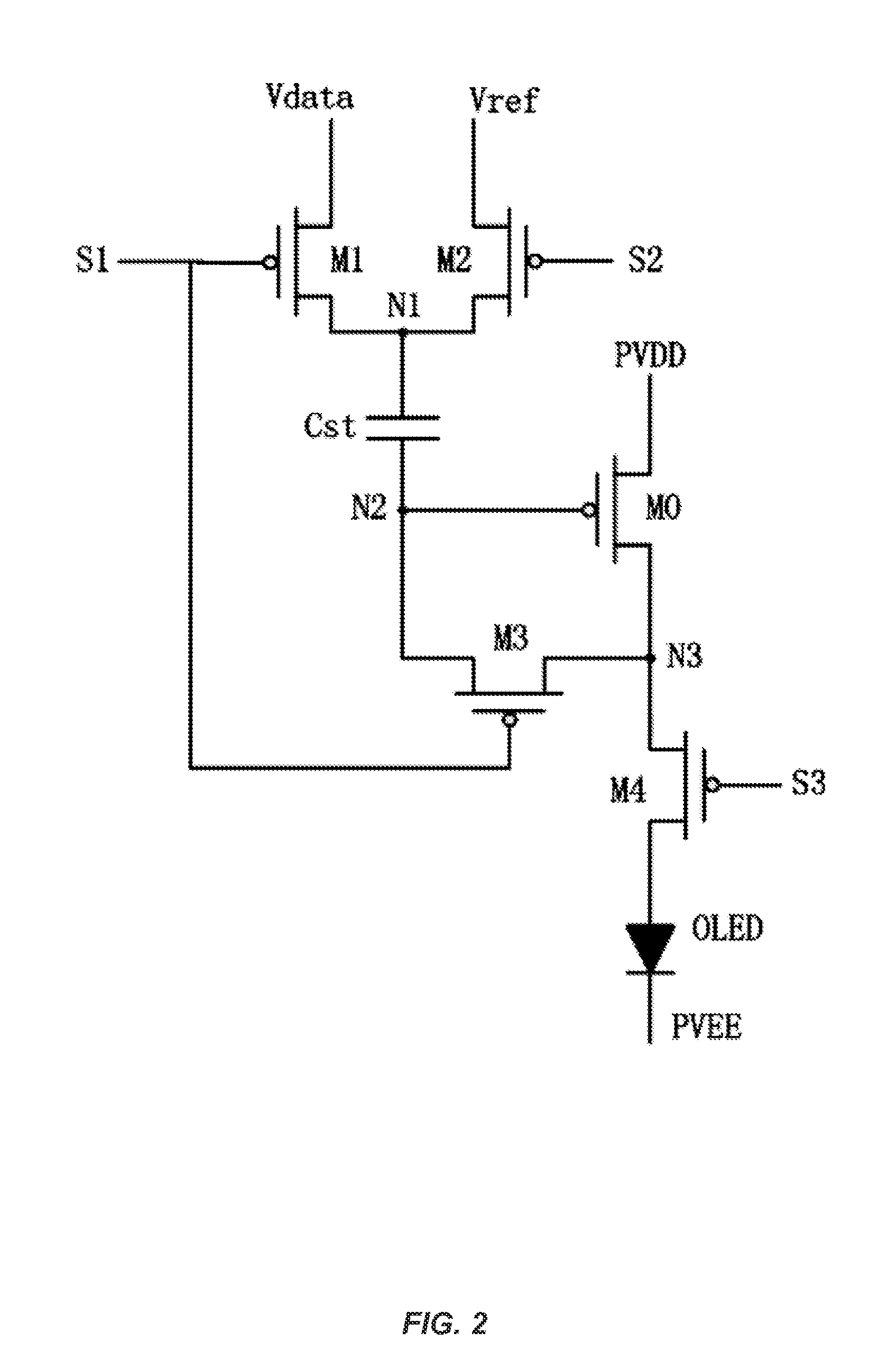
[0028]FIG. 2 is a schematic view of a pixel compensation circuit for an organic light emitting display according to an embodiment of the present invention. As shown in FIG. 2, the pixel compensation circuit of this embodiment includes a first transistor M1, a second transistor M2, a third transistor M3, a fourth transistor M4, a driving transistor M0, a capacitor Cst, and an organic light emitting element OLED.

[0029]A first electrode of the first transistor M1 is connected to a data signal line to receive a da...


PUM


Abstract

The present invention discloses a pixel compensation circuit and method for an organic light emitting display. The circuit comprises a first transistor, a second transistor, a third transistor, a fourth transistor, a driving transistor, a capacitor, and an organic light emitting element. The first transistor transmits a data signal to a first plate of the capacitor; the second transistor applies a reference voltage to the first plate of the capacitor; the driving transistor determines a magnitude of a driving current; the third transistor establishes a connection between the gate electrode and the drain electrode of the driving transistor; the fourth transistor passes the driving current from the driving transistor to the organic light emitting element; and the organic light emitting element emits light in response to the driving current.

Description

CROSS-REFERENCES TO RELATED APPLICATIONS[0001]This application claims the benefit of priority to Chinese Patent Application No. 201310746962.7, filed with the Chinese Patent Office on Dec. 30, 2013 and entitled “PIXEL COMPENSATION CIRCUIT AND METHOD FOR ORGANIC LIGHT EMITTING DISPLAY”, the content of which is incorporated herein by reference in its entirety.TECHNICAL FIELD[0002]The present invention relates to the field of organic light emitting display technologies, in particular to an organic light emitting display, and a pixel compensation circuit and method for an organic light emitting display.BACKGROUND OF THE INVENTION[0003]An organic light emitting display is a film light emitting device made of organic semi-conductive material and driven by a direct current voltage, and the film light emitting device includes a glass substrate and a very thin layer of organic material coated on the glass substrate. When current flows through the organic material, the organic material emits ...

Claims


Application Information

Patent Timeline
Patent Type & Authority Applications(United States)
IPC IPC(8): G09G3/32
CPCG09G3/3233G09G2320/0233G09G2300/0819G09G2320/045G09G2300/0861G09G2310/0251
Inventor QIAN, DONGGU, HANYUZHANG, TONG
Owner SHANGHAI TIANMA MICRO ELECTRONICS CO LTD
Why Eureka
Try Eureka