Video wall control system and method

a control system and video wall technology, applied in the field of video wall control system, can solve the problems of increasing manufacturing cost, inconvenient use for users, and inability to monitor people from a control center, so as to improve convenience, increase context awareness of users, and set freely and conveniently

Active Publication Date: 2015-07-02
HANWHA VISION CO LTD
View PDF4 Cites 14 Cited by
  • Summary
  • Abstract
  • Description
  • Claims
  • Application Information

AI Technical Summary

Benefits of technology

[0016]According to the exemplary embodiments, it is possible to control CCTV images, split images and monitor merge / unmerge operations all together through a single control process and thus to improve convenience.
[0017]In addition, since a maximum of 36 monitors can be connected, it is possible to allow a video wall to be set freely and conveniently, and it is also possible to properly monitor multiple individuals from a control center.
[0018]Moreover, it is possible to acquire a considerable number of CCTV images and thus to provide a “sequence” function based on the acquired CCTV images. Also, it is possible to provide three different types of “spot” functions (such as wall, monitor and tile modes) for an immediate notification of any event occurred and thus to allow security personnel to properly install and set up a video wall in consideration of the characteristics of a place where the video wall needs to be provided. Also, it is possible to heighten the context awareness of users by precisely detecting any event occurred and notifying the users of the results of the detection.

Problems solved by technology

Also, the related-art video wall systems of FIGS. 1A and 1B request instructions to be entered and processed for each control process, thereby causing inconvenience to users.
Also, most software for controlling a CCTV screen is designed for use in user personal computers (PCs), and thus cannot be used to monitor people from a control center.
Also, in the related-art video wall systems of FIGS. 1A and 1B, the wall controller 11 and the matrix switcher 15 are both needed, thereby causing an increase in manufacturing cost.
Also, since multiple video walls cannot be controlled with a single personal computer (PC), monitor extensibility and freedom may deteriorate.

Method used


Image

  • Video wall control system and method
  • Video wall control system and method
  • Video wall control system and method

Examples


Embodiment Construction

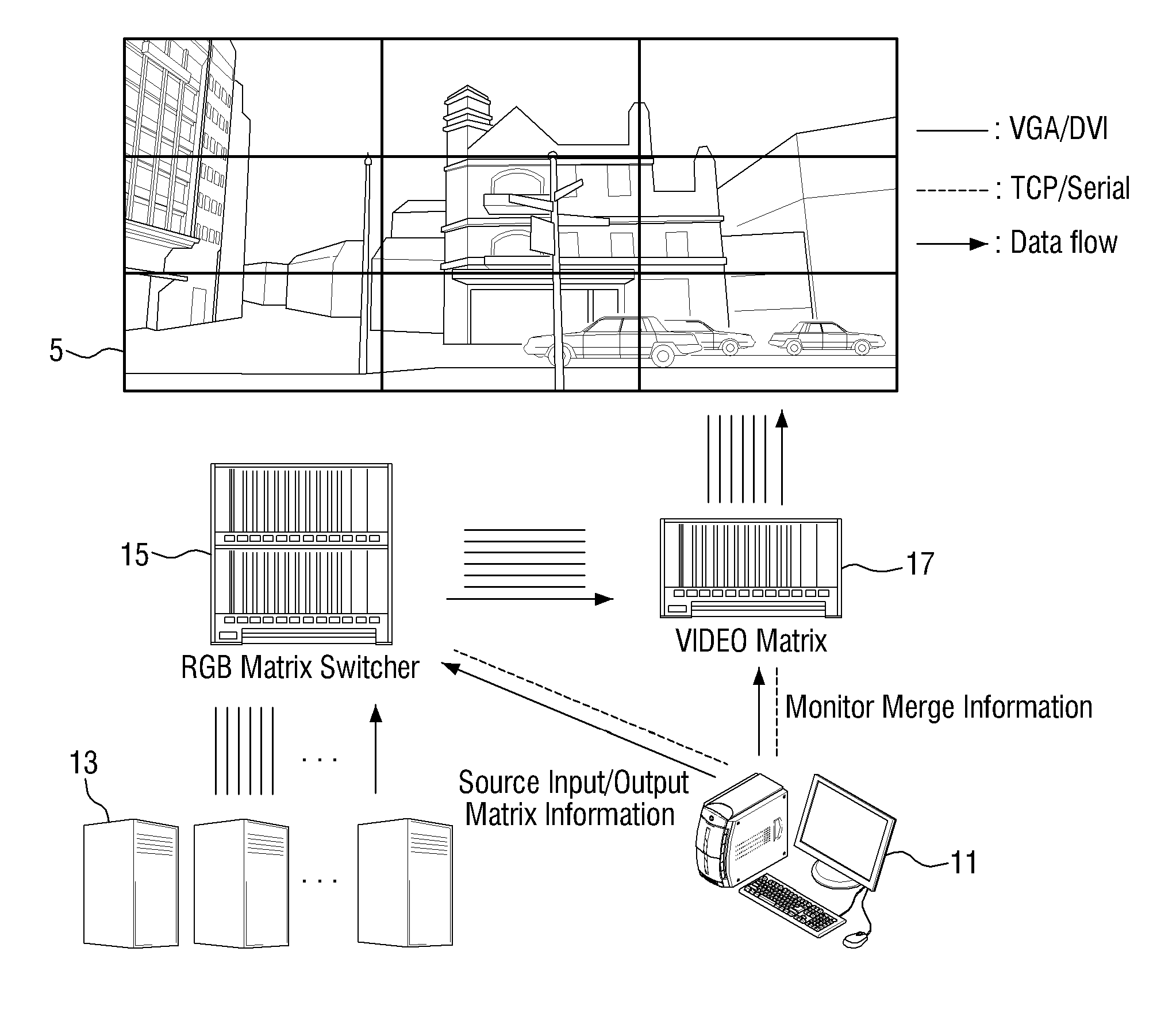
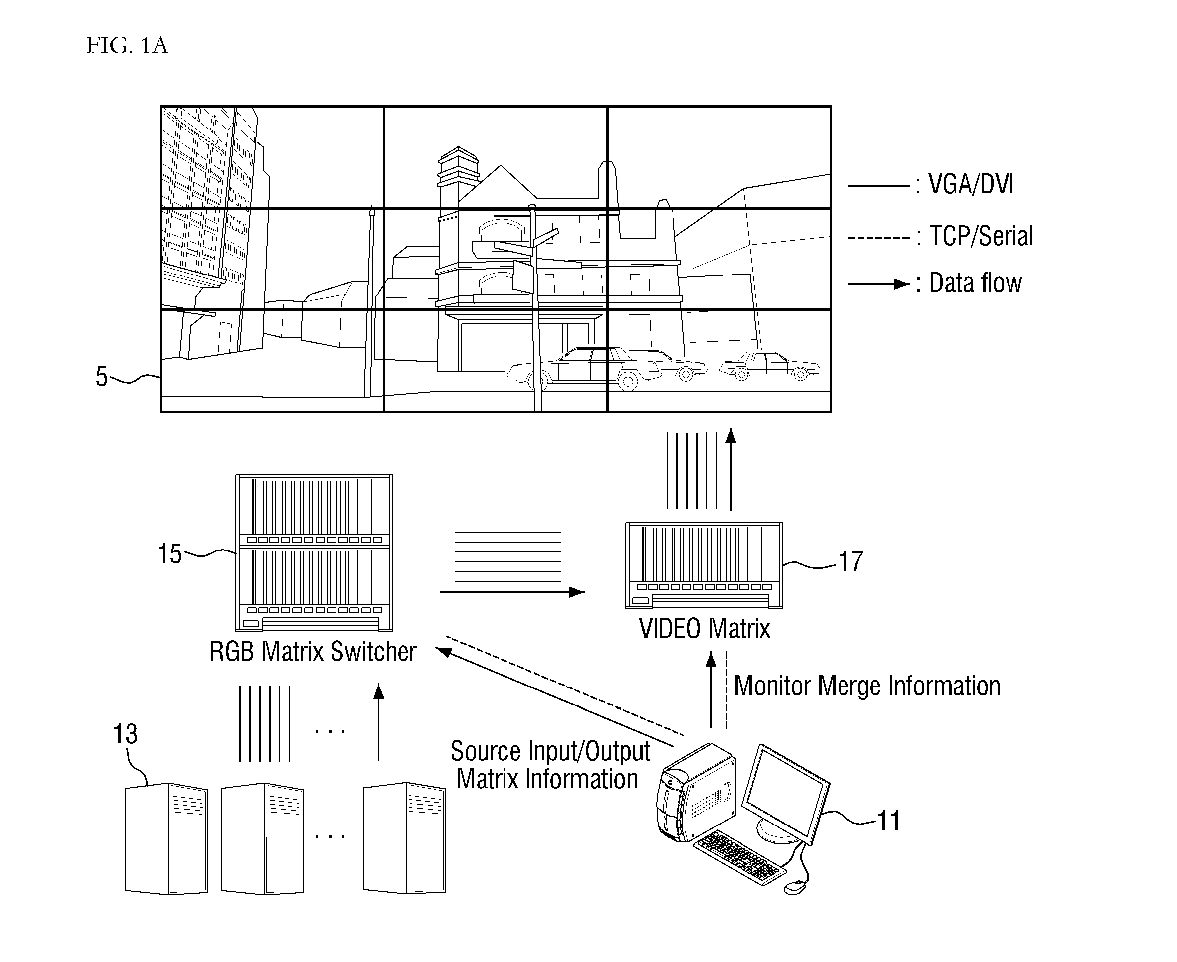
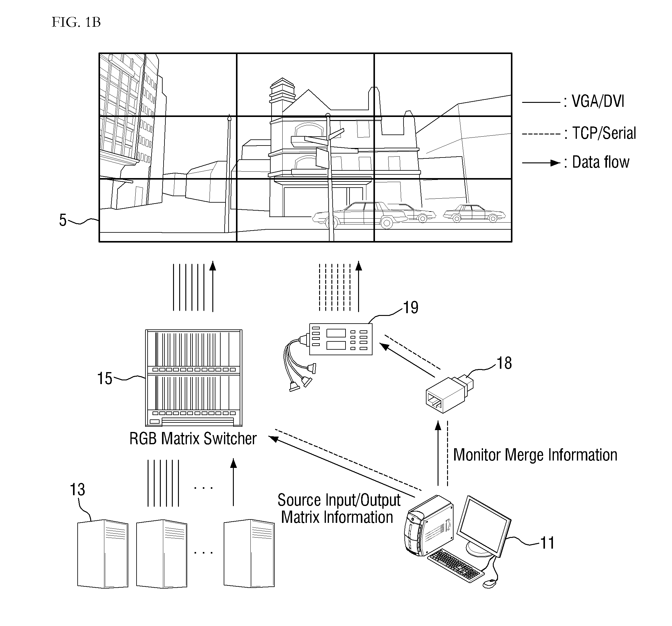
[0026]The inventive concept will now be described more fully hereinafter with reference to the accompanying drawings, in which exemplary embodiments of the inventive concept are shown. This inventive concept may, however, be embodied in different forms and should not be construed as limited to the embodiments set forth herein. Rather, these embodiments are provided so that this disclosure will be thorough and complete, and will fully convey the scope of the inventive concept to those skilled in the art. The same reference numbers indicate the same components throughout the specification.

[0027]It will be understood that, although the terms first, second, etc. may be used herein to describe various elements, these elements should not be limited by these terms. These terms are only used to distinguish one element from another element. Thus, for example, a first element, a first component or a first section discussed below could be termed a second element, a second component or a second...


PUM


Abstract

A video wall control system for controlling a video wall including a plurality of screens, the video wall control system including: at least one client module controlling the layout of the video wall; a central control module acquiring camera unique identification (UID) and a video stream from a monitoring system, storing the camera UID and the video stream, and controlling the layout of the video wall; a storage module storing the modified video wall layout; a gateway module receiving a layout modification event from the client module or the central control module and load the modified video wall layout from the storage module; and a decoding module loading the camera UID and the video stream from the central control module, receiving the modified video wall layout from the gateway module, and modifying the layout of the video wall based on the received modified video wall layout.

Description

CROSS-REFERENCE TO RELATED PATENT APPLICATION[0001]This application claims priority from Korean Patent Application No. 10-2013-0164157 filed on Dec. 26, 2013 in the Korean Intellectual Property Office, the disclosure of which is incorporated herein in its entirety by reference.BACKGROUND[0002]1. Field[0003]Apparatuses and methods consistent with exemplary embodiments of the inventive concept relate to a video wall control system, and more particularly, to a video wall control system which performs real-time monitoring and control closed circuit television (CCTV) images, split screens, and monitor merge / unmerge operations all together through a single control process by acquiring a considerable number of CCTV screens at the same time.[0004]2. Description of the Related Art[0005]Most buildings today are equipped with security systems and security personnel for monitoring the security systems. Video wall systems are systems that can be built in the security office in a building for all...

Claims


Application Information

Patent Timeline
Patent Type & Authority Applications(United States)
IPC IPC(8): G09G5/00
CPCG09G2300/026G09G5/003G06F3/1446H04N5/268H04N7/181H04N5/45H04N7/18
Inventor KIM, DAE SANGYUN, YOUNG IN
Owner HANWHA VISION CO LTD
Why Eureka
Try Eureka