Spark plug

a plug and plug technology, applied in the field of spark plugs, can solve the problems of deterioration of mechanical strength, reduction of the diameter of the insulator, and deterioration of the mechanical strength of the insulator

Active Publication Date: 2015-07-02
NGK SPARK PLUG CO LTD
View PDF5 Cites 13 Cited by
  • Summary
  • Abstract
  • Description
  • Claims
  • Application Information

AI Technical Summary

Problems solved by technology

However, reducing the size or diameter of the spark plug is accompanied by a reduction in the diameter of an insulator, so that the mechanical strength of the insulator deteriorates.
A deterioration in mechanical strength of the insulator may affect the performance of the spark plug.

Method used


Image

  • Spark plug
  • Spark plug
  • Spark plug

Examples


first embodiment

A. First Embodiment

A-1. Configuration of Spark Plug

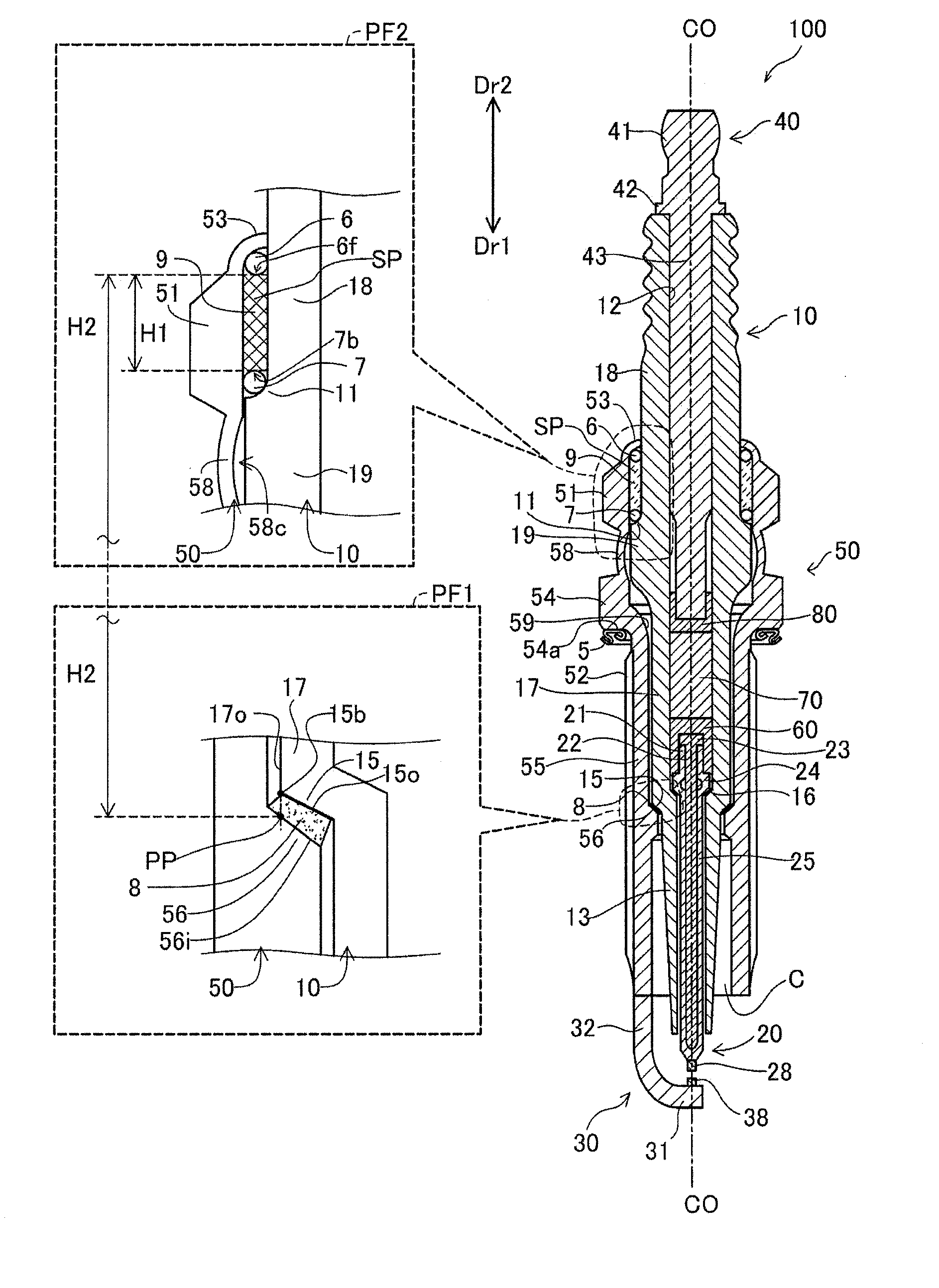
[0089]A first embodiment of the present invention will next be described. FIG. 1 is a sectional view of a spark plug 100 of the present embodiment. The dot-dash line in FIG. 1 indicates a center axis CO of the spark plug 100. The center axis CO may also be called the axial line CO. A direction (a vertical direction in FIG. 1) in parallel with the center axis CO is called the axial direction. A downward direction in FIG. 1 is called a first direction Dr1, and an opposite direction of the first direction Dr1 is called a second direction Dr2. The first direction Dr1 is a direction directed from a portion of the spark plug 100 located externally of a combustion chamber to a portion of the spark plug 100 inserted into the combustion chamber. A side of the spark plug 100 in the first direction Dr1 may be called a “forward side,” and a side of the spark plug 100 in the second direction Dr2 may be called a “rear side.” Ends of various membe...

second embodiment

B. Second Embodiment

[0183]FIG. 9 is a partially sectional view showing a spark plug 1100 according to a second embodiment of the present invention. FIG. 9 shows a front view of the appearance of the spark plug 1100 at the right side of the axial line CO represented by a dot-dash line, and a sectional view of the spark plug 1100 taken along the center axis of the spark plug 1100 at the left side of the axial line CO. In the following description, the axially lower side (Dr1 side) of the spark plug 1100 is referred to as the forward side of the spark plug 1100, and the axially upper side (Dr2 side) as the rear side. The spark plug 1100 includes a ceramic insulator 1010, a center electrode 1020, a ground electrode 1030, a terminal electrode 1040, and a metallic shell 1050.

[0184]The ceramic insulator 1010 is a tubular insulator having an axial hole 1012 which is formed at its center and accommodates therein the center electrode 1020 and the terminal electrode 1040. The axial hole 1012 e...

third embodiment

C. Third Embodiment

[0217]FIG. 15 is an enlarged sectional view showing a packing 1208 and its periphery of a spark plug 1200 according to a third embodiment of the present invention. In the following description, component members of the spark plug 1200 are denoted by reference numerals whose last two digits are identical with the last two digits of reference numerals assigned to corresponding component members of the spark plug 1100 (see FIGS. 9 and 10). The spark plug 1200 of the third embodiment differs from the spark plug of the second embodiment only in the mode of the packing 1208 and is identical to the spark plug of the second embodiment in other configurational features. The following description discusses only the difference from the second embodiment.

[0218]As shown in FIG. 15, the packing 1208 is disposed between a diameter reducing portion 1215 of a ceramic insulator 1210 and a diameter reducing portion 1262 of a metallic shell 1250 and between a forward trunk portion 12...


PUM


Abstract

A spark plug includes a center electrode, an insulator, a metallic shell, and a seal member for providing a seal between the insulator and the metallic shell. The insulator includes a first portion, a second portion located axially forward of the first portion and being smaller than the first portion, and an insulator first-diameter-reducing-portion whose outside diameter reduces forward and which connects the first portion and the second portion. The metallic shell includes a protrusion that includes a metallic shell diameter-reducing-portion whose inside diameter reduces forward. The seal member is disposed between the insulator first-diameter-reducing-portion and the metallic shell diameter-reducing-portion. A relationship θ21>θ22 is satisfied, where the angle θ21 is an angle between a straight line orthogonal to the axial line and the outline of the metallic shell diameter-reducing-portion, and the angle θ22 is an angle between the straight line and an outline of the insulator first-diameter-reducing-portion.

Description

CROSS-REFERENCE TO RELATED PATENT APPLICATIONS[0001]This application is a U.S. National Phase application under 35 U.S.C. §371 of International Patent Application No. PCT / JP2013 / 002936, filed May 7, 2013, and claims the benefit of Japanese Patent Applications No. 2012-158280, filed on Jul. 17, 2012, and No. 2012-187283, filed Aug. 28, 2012, all of which are incorporated by reference in their entirety herein. The International application was published in Japanese on Jan. 23, 2014 as International Publication No. WO / 2014 / 013654 under PCT Article 21(2).FIELD OF THE INVENTION[0002]The present invention relates to a spark plug for an internal combustion engine.BACKGROUND OF THE INVENTION[0003]A spark plug for use in an internal combustion engine is required to reduce its size or diameter for the purpose of, for example, improving the degree of freedom for design of the internal combustion engine. Specifically, as a result of reducing the diameter of the spark plug, a mounting hole for t...

Claims


Application Information

Patent Timeline
Patent Type & Authority Applications(United States)
IPC IPC(8): H01T13/36
CPCH01T13/36H01B3/12
Inventor OZEKI, KEIJIKATO, TOMOAKIMUKOYAMA, NAOYUKI
Owner NGK SPARK PLUG CO LTD
Why Eureka
Try Eureka