
Apparatus and method for simultaneously transmitting and receiving orbital angular momentum (OAM) modes

a technology of orbital angular momentum and apparatus, which is applied in the direction of multimode transmission, fibre transmission, multi-antenna system, etc., can solve the problems of difficult manufacturing of super high frequency apparatus that operates as beam splitter and beam combiner, and the structure of optical communication system may be unusable,

Inactive Publication Date: 2015-07-02
ELECTRONICS & TELECOMM RES INST
View PDF29 Cites 36 Cited by
  • Summary
  • Abstract
  • Description
  • Claims
  • Application Information

AI Technical Summary

Benefits of technology

The present invention provides an apparatus and method to simultaneously transmit or receive different orbital angular momentum (OAM) modes for electromagnetic waves. This allows for the use of OAM modes as independent communication channels in an invisible electromagnetic wave band. The apparatus includes a mode multiplexing apparatus and a matrix array antenna, which outputs OAM modes for electromagnetic waves based on mode signals. The modes are generated by mixing and distributing input signals, and shifting their phases using phase shifters. The output signals have different phases and amplitudes. The matrix array antenna has multiple element antennas arranged in a 2D matrix to output the mode signals. The mode demultiplexing apparatus restores the input signals by mixing and distributing the mode signals, and shifting their phases using phase shifters. The invention thus allows for the efficient transmission and reception of OAM modes for electromagnetic waves.

Problems solved by technology

However, when the OAM technique is applied to an invisible wireless communication system using an electromagnetic wave, a structure of the optical communication system may be unusable.
Dissimilar to laser beams used for optical communication, it is difficult to concentrate electronic waves used for wireless communication on a narrow area with high density.
Thus, manufacturing of a super high frequency apparatus that operates as the beam splitter and the beam combiner may be difficult.

Method used


Image

  • Apparatus and method for simultaneously transmitting and receiving orbital angular momentum (OAM) modes
  • Apparatus and method for simultaneously transmitting and receiving orbital angular momentum (OAM) modes
  • Apparatus and method for simultaneously transmitting and receiving orbital angular momentum (OAM) modes

Examples


Embodiment Construction

[0032]Hereinafter, embodiments of the present invention will be described in detail with reference to the accompanying drawings. A method of transmitting orbital angular momentum (OAM) modes and a method of receiving OAM mode according to an embodiment of the present invention may be performed by an apparatus for transmitting OAM modes and an apparatus for receiving OAM modes, respectively.

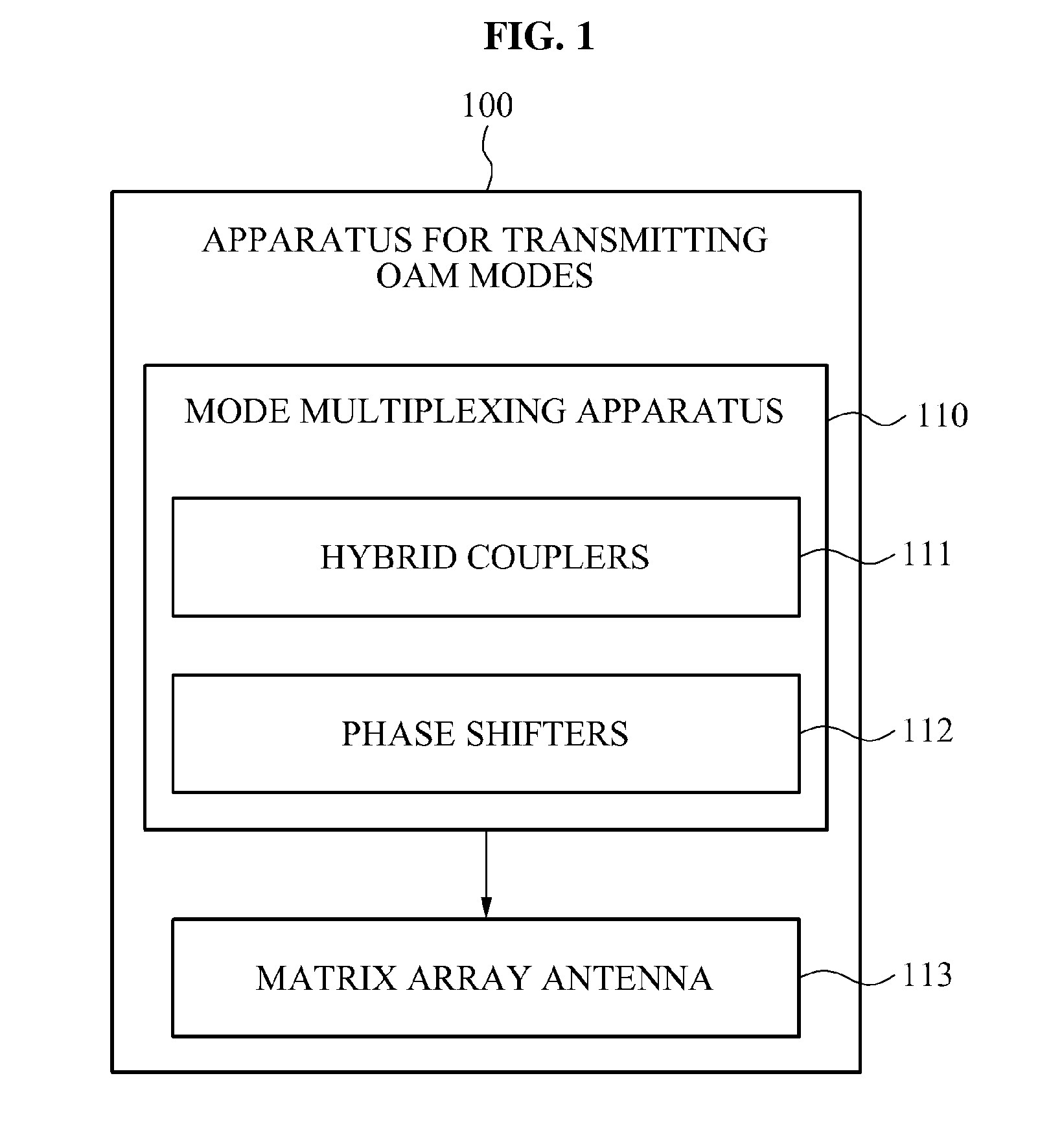
[0033]FIG. 1 is a block diagram illustrating an apparatus 100 for transmitting OAM modes according to an embodiment of the present invention.

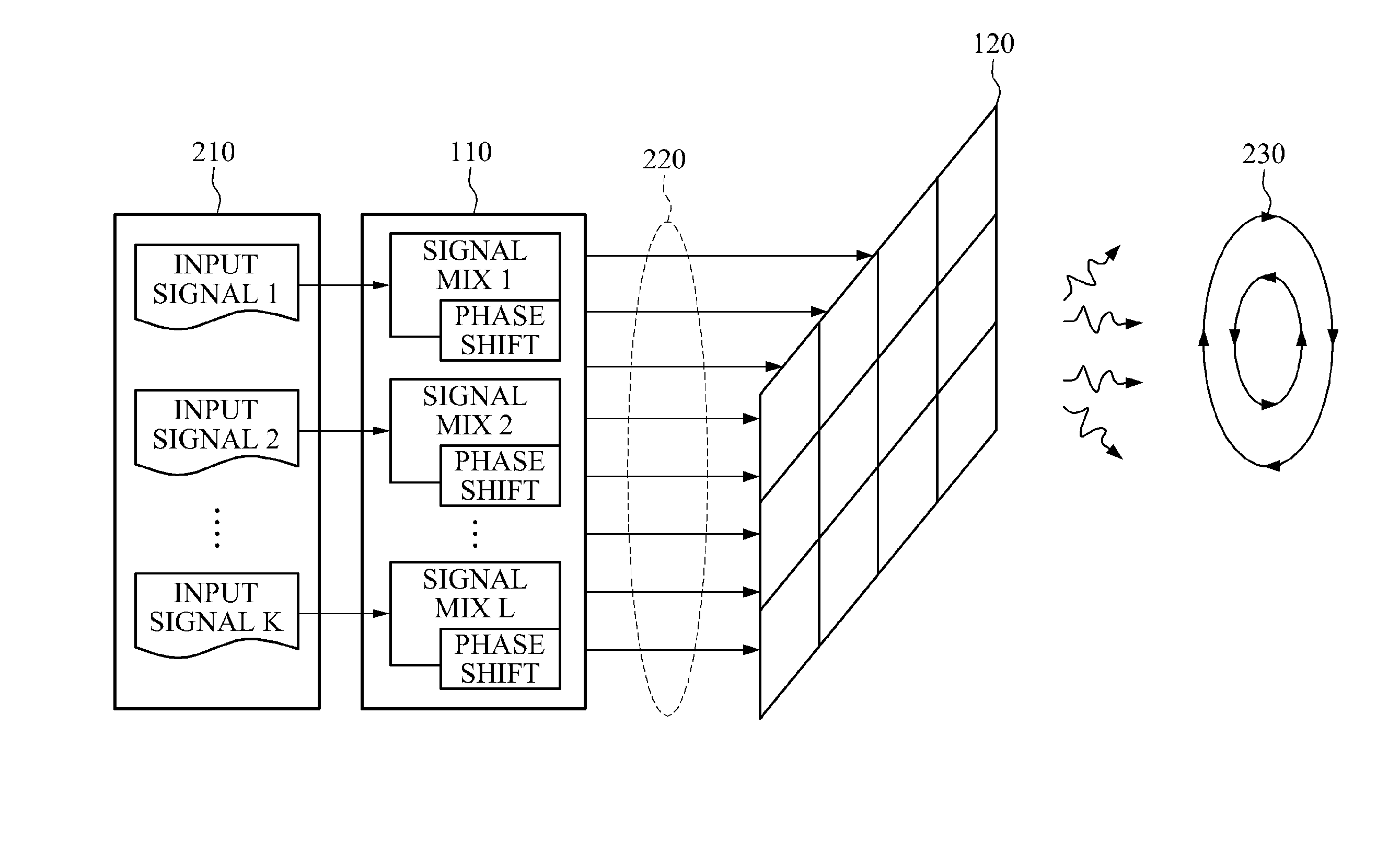
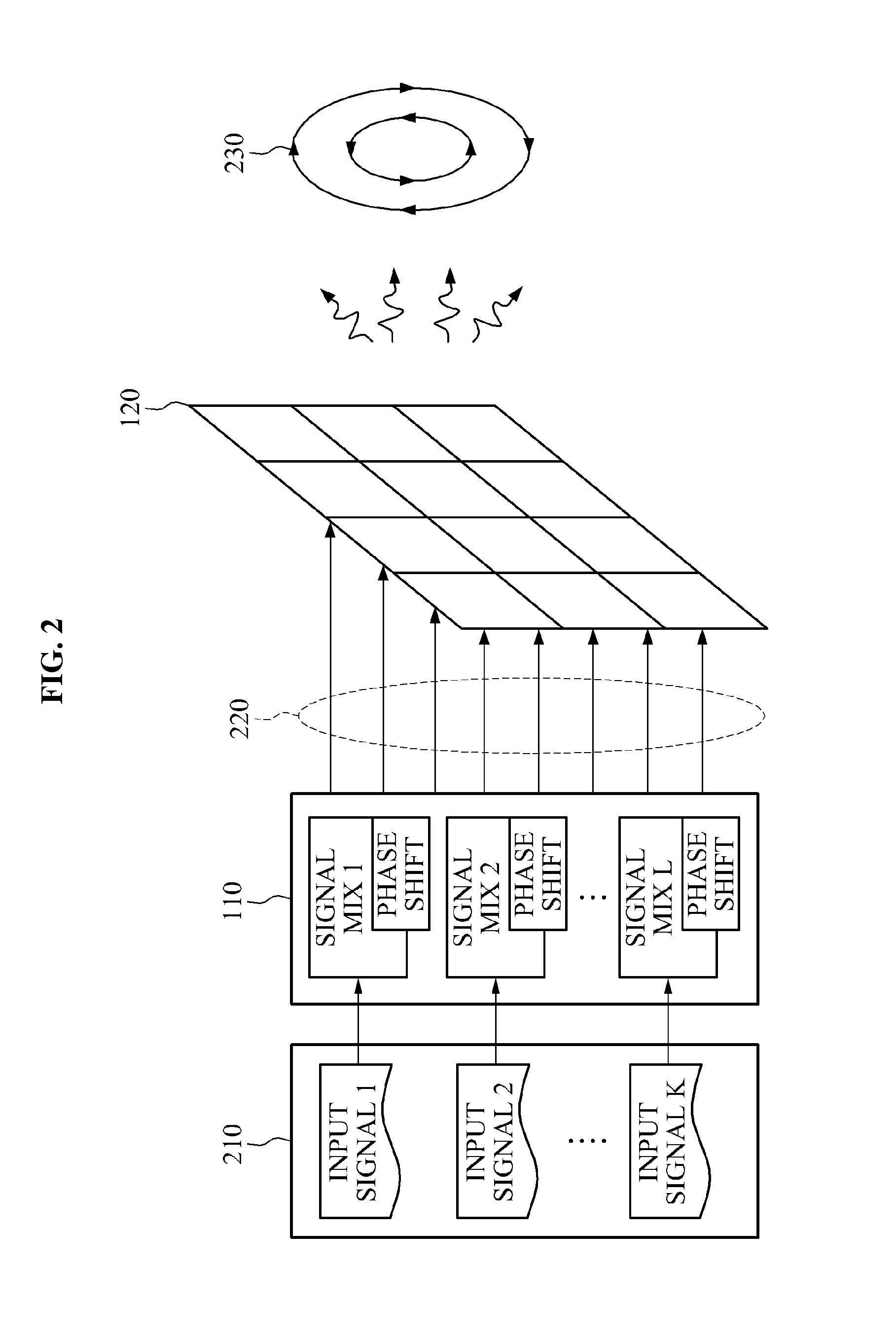
[0034]Referring to FIG. 1, the apparatus 100 for transmitting OAM modes includes a mode multiplexing apparatus 110 and a matrix array antenna 120.

[0035]The mode multiplexing apparatus 110 may generate a plurality of mode signals based on a plurality of input signals.

[0036]The mode signals may be signals input into the matrix array antenna 120 to enable the matrix array antenna 120 to output OAM modes for electromagnetic waves. A number of the input signals ma...


PUM


Abstract

Provided is an apparatus and method for simultaneously transmitting and receiving orbital angular momentum (OAM) modes. An apparatus for transmitting OAM modes may include a mode multiplexing apparatus, and a matrix array antenna configured to output OAM modes for electromagnetic waves based on mode signals, wherein the mode multiplexing apparatus may include hybrid couplers configured to generate a plurality of output signals having different phases and different amplitudes by mixing and distributing a plurality of input signals, and phase shifters configured to generate the mode signals by shifting the phases of the output signals.

Description

CROSS-REFERENCE TO RELATED APPLICATION[0001]This application claims the benefit of Korean Patent Application No. 10-2013-0168992, filed on Dec. 31, 2013, in the Korean Intellectual Property Office, the disclosure of which is incorporated herein by reference.BACKGROUND[0002]1. Field of the Invention[0003]Embodiments of the present invention relate to an apparatus and method for simultaneously transmitting and receiving orbital angular momentum (OAM) modes, and more particularly, to an apparatus and method that may restore an input signal by simultaneously transmitting or receiving electromagnetic wave signals having OAM modes through a matrix array antenna.[0004]2. Description of the Related Art[0005]An orbital angular momentum (OAM) relates to a technique that transmits or receives an electromagnetic wave using an electromagnetic wave mode, and is used for a waveguide or a transmission line. Electromagnetic wave modes may be orthogonal to each other and independently transmit electr...

Claims


Application Information

Patent Timeline
Patent Type & Authority Applications(United States)
IPC IPC(8): H04J14/04
CPCH04J14/04H04B10/2581H04B10/70H04J14/07H04B7/02
Inventor BYUN, WOO JINCHO, YONG HEUIKIM, KWANG SEONKIM, BONG SUKANG, MIN SOOLIM, JONG SOO
Owner ELECTRONICS & TELECOMM RES INST
Learn More