Elongated member for medical use and cleaning device

a cleaning device and member technology, applied in the field of elongated members, can solve the problems of difficult to realize an endoscope having a reduced diameter, difficult to obtain a clear image, and large device configuration of the endoscope, etc., and achieve the effect of enlarged diameter

Inactive Publication Date: 2015-07-09
TERUMO KK
View PDF4 Cites 18 Cited by
  • Summary
  • Abstract
  • Description
  • Claims
  • Application Information

AI Technical Summary

Benefits of technology

[0006]Disclosed here is an elongated member for medical use that, with a cleaning function, can be applied to a medical instrument having an elongated main body section, such as an endoscope, while preventing the device

Problems solved by technology

In the use of an endoscope, when various body fluids, secretions or the like present in a living body are deposited on the lens, it may be impossible to obtain a clear image.
In the technology described in Japanese Patent Laid-Open No. 2012-86021, however, although cleaning of the lens is possible, there are some problems.
Consequently, t

Method used


Image

  • Elongated member for medical use and cleaning device
  • Elongated member for medical use and cleaning device
  • Elongated member for medical use and cleaning device

Examples


first embodiment

[0047]Some embodiments, disclosed by way of example, of the present disclosure will now be described below. Note that for convenience of explanation, the dimensional ratios in the drawings may be exaggerated and be different from the actual ratios. In the following description, the hand operation side of a cleaning device 1 according to a first embodiment of the present disclosure will be referred to as the “proximal side,” and the side of insertion into a living-body lumen as the “distal side.”

[0048]A configuration of the cleaning device 1 according to the first embodiment of the present disclosure will be described.

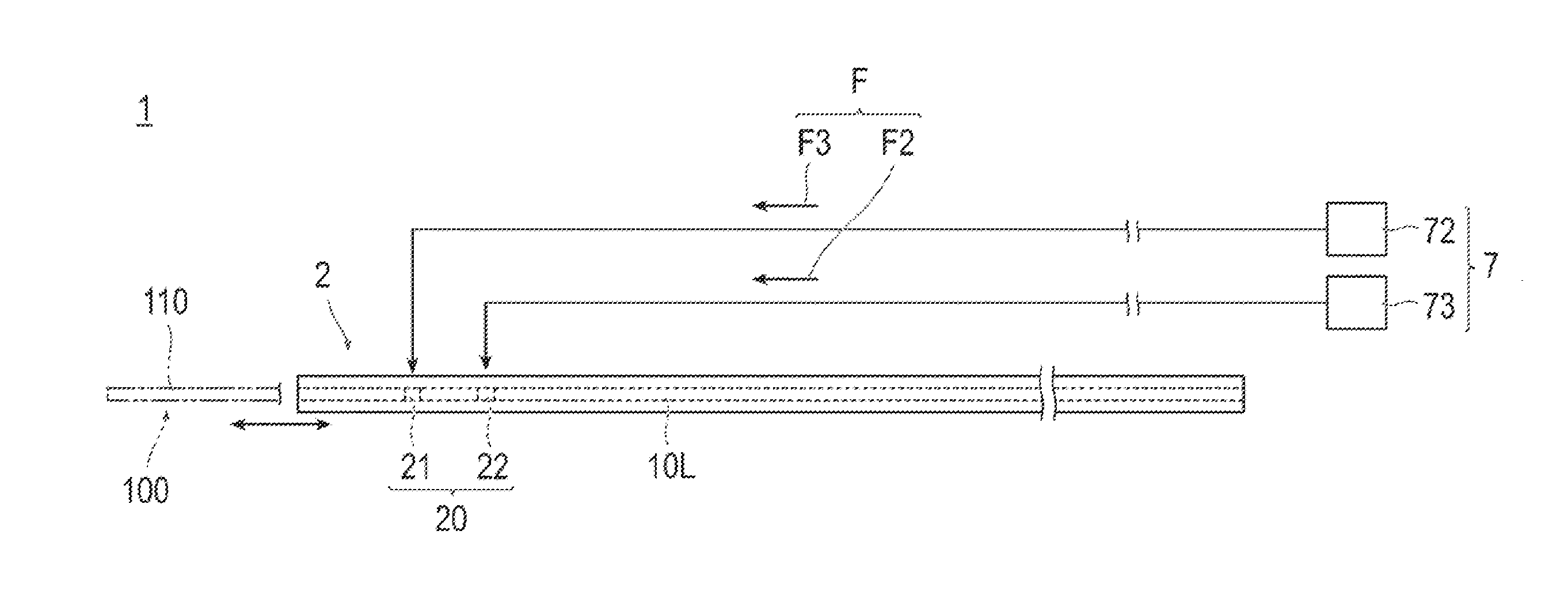
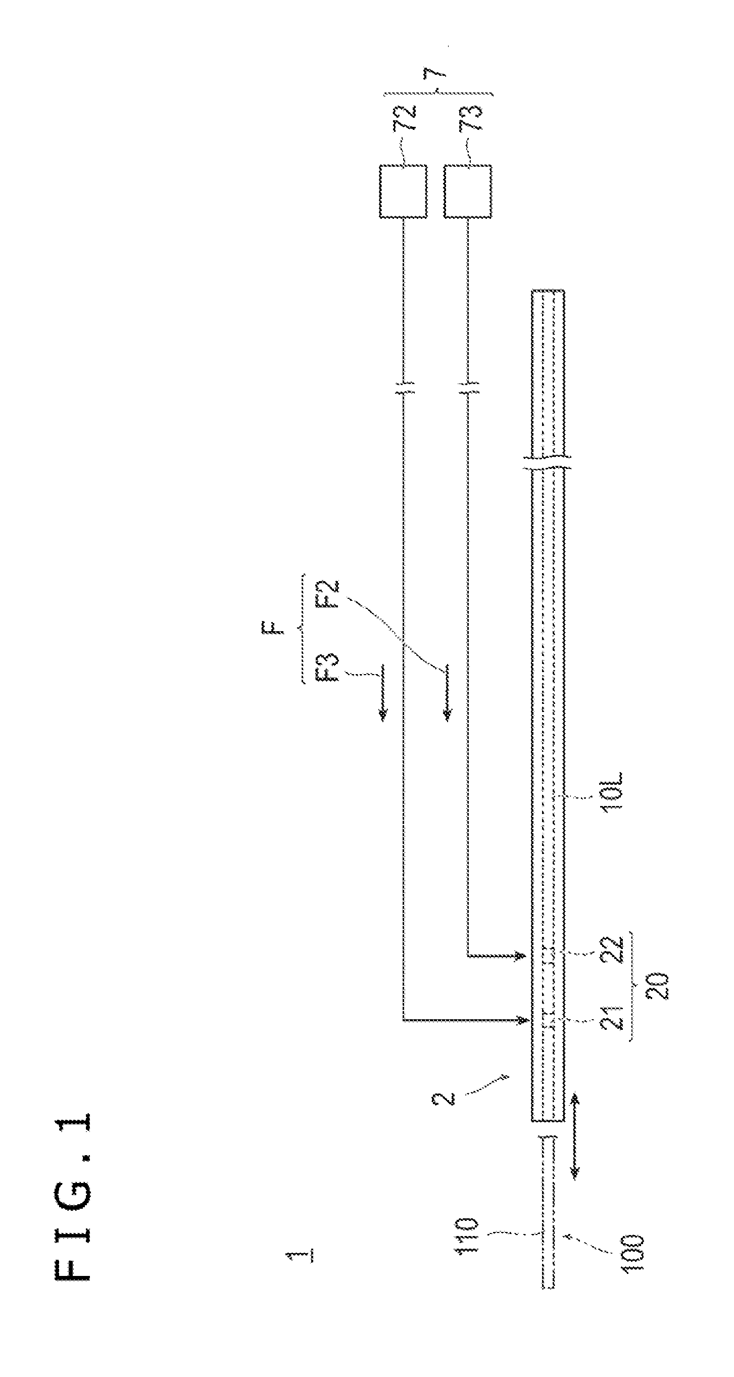
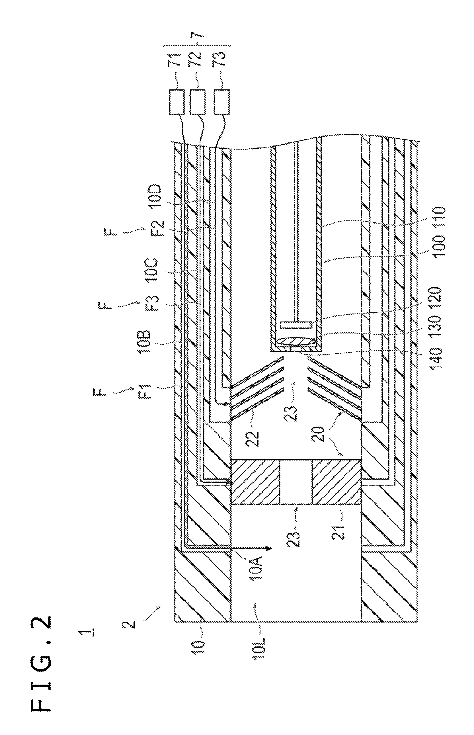
[0049]FIG. 1 is a schematic view showing the cleaning device 1 according to the first embodiment of the present disclosure, and FIG. 2 is a side sectional view showing the cleaning device 1 according to the first embodiment of the present disclosure.

[0050]The cleaning device 1 according to the first embodiment of the present disclosure will be outlined as follows. As sh...

second embodiment

[0089]A second embodiment of the present disclosure will be described below. In the following, descriptions of those features that are common to the first and second embodiments will be omitted, and features that are characteristic of only the second embodiment will be described.

[0090]FIG. 4 is a side sectional view showing a cleaning device 5 according to the second embodiment of the present disclosure. FIG. 5 is a sectional view taken along line 5-5 of FIG. 4.

[0091]As shown in FIGS. 4 and 5, the cleaning device 5 according to the second embodiment of the present disclosure includes an elongated member 6 for medical use and a supply / suction unit 8. The elongated member 6 includes: a main body section 210 being flexible and having a hollow elongated shape; a cleaning unit 220 adapted to clean an imaging device 100; an outer tube 230 adapted to guide a fluid F to the cleaning unit 220; a seal section 240 adapted to control a flow of the fluid F; and a retention amount control unit 25...

modification 1

[0117]In the first and second embodiments described above, the supply / suction unit 7 and 8 supplies the fluid F to the first contact member 21 and 221 and the second contact member 22 and 222 and into the lumen 10L, and the supply / suction port 10A supplies the fluid F into the lumen 10L therethrough. However, the supply / suction unit 7 and 8 may suck the liquid out of the first contact member 21 and 221, the second contact member 22 and 222 and the lumen 10L, and the supply / suction port 10A may serve for sucking the liquid out of the lumen 10L therethrough. For instance, the second lumen 10C in the first embodiment may be used as a suction lumen for sucking out a liquid therethrough, and the second supply / suction unit 72 may suck the liquid out of the first contact member 21, whereby the amount of liquid retained by the first contact member 21 can be reduced. This ensures that dry wiping can be carried out in the condition where the first contact member 21 is retaining a more reduced...


PUM


Abstract

An elongated member for medical use includes a lumen into which a medical instrument having an elongated main body section is insertable, the lumen being configured such that the medical instrument is advanceable and recedable through the lumen; and a cleaning unit configured to make contact with at least a portion of the medical instrument so as to clean the medical instrument when the medical instrument is advanced and receded through the lumen.

Description

CROSS-REFERENCE TO RELATED APPLICATIONS[0001]This application is a continuation application filed under 35 U.S.C. 111(a) claiming the benefit under 35 U.S.C. §§120 and 365(c) of PCT International Application No. PCT / JP2013 / 074570 filed on Sep. 11, 2013, which is based upon and claims the benefit of priority of Japanese Application No. 2012-215664 filed on Sep. 28, 2012, the entire contents of which are hereby incorporated by reference in their entireties.BACKGROUND[0002]The present disclosure relates to an elongated member for medical use that is used for cleaning a medical instrument and to a cleaning device including the elongated member.[0003]In carrying out various procedures or treatments in living bodies, using an imaging device such as an endoscope to obtain images is commonly practiced. Such an imaging device normally includes an elongated main body section and a lens attached to the distal end (tip) of the main body section. In use, the main body section is pushed forward i...

Claims


Application Information

Patent Timeline
IPC IPC(8): A61B1/12A61B1/04A61B1/00A61B19/00
CPCA61B1/122A61B19/34A61B1/127A61B2019/343A61B1/128A61B1/04A61B1/00163A61B1/125A61B1/00135A61B1/126A61B1/044
Inventor SUEHARA, SATORUNAKANO, TAIGAMOMOKI, HIDEYUKI
Owner TERUMO KK
Why Eureka
Try Eureka