Centrifugal multiple-impeller electric pump

a technology of electric pumps and impellers, applied in the direction of piston pumps, non-positive displacement fluid engines, liquid engines, etc., can solve the problems of complicated design, and insufficient so as to reduce inner leakage, reduce load, and increase pump service life and operation reliability

Inactive Publication Date: 2015-07-09
YAZYKOV ANDREY YURIEVICH
View PDF5 Cites 10 Cited by
  • Summary
  • Abstract
  • Description
  • Claims
  • Application Information

AI Technical Summary

Benefits of technology

[0009]Technical result providing the solution of this task is increasing pump service life and operation reliability by means of reducing inner leakages and ensuring less loads on pump body and separating membrane caused by pressure developed by the impellers, using better design of intermediate body, and positioning thermal switch outside of oil filled volume of the pump. Electric motor shaft bearing being molded simultaneously with end shield molding is also meant to increase pump service life and operation reliability.

Problems solved by technology

Shortcomings of pumps known in the art are complicated design and insufficient service life and operation reliability due to increased inner leakages and loads on pump case and separating membrane caused by pressure developed by the impellers and delivered by the pump.
Shortcomings of pumps known in the art are complicated design and insufficient service life and operation reliability due to increased inner leakages and loads on pump body and separating membrane caused by pressure developed by the impellers and delivered by the pump.

Method used


Image

  • Centrifugal multiple-impeller electric pump
  • Centrifugal multiple-impeller electric pump
  • Centrifugal multiple-impeller electric pump

Examples


embodiment

Preferred Embodiment

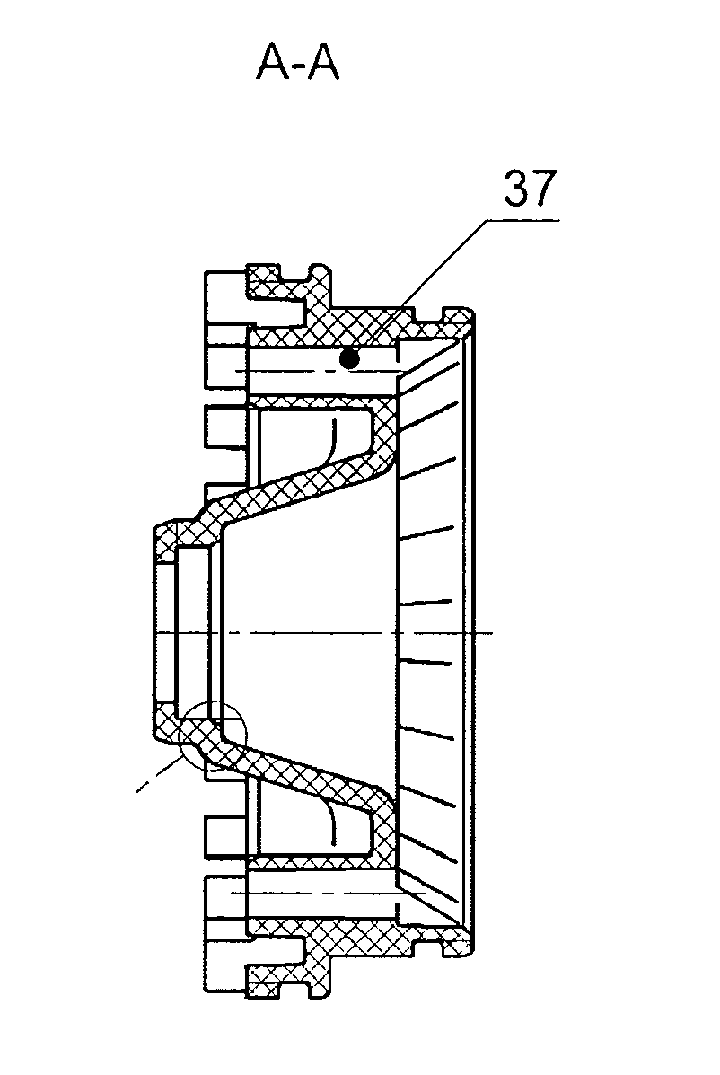
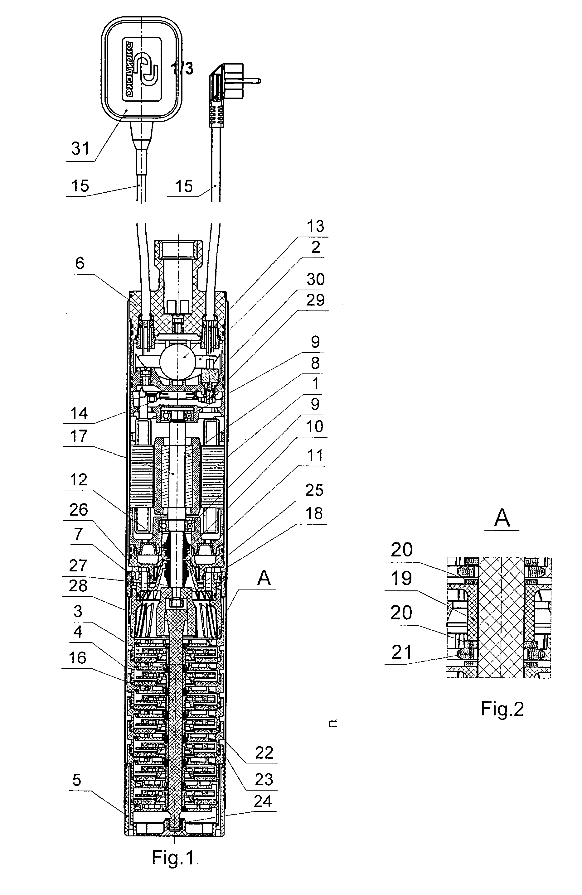
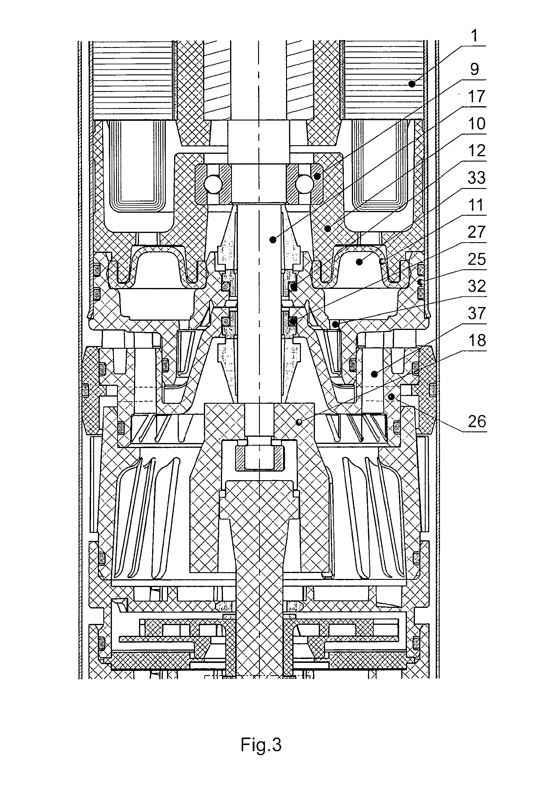
[0025]Electric pump works as follows. The pumped fluid enters the holes in the mesh cover 5. Then, due to the rotation of impellers 19 of the Impeller package 3, pumped fluid gets increments of kinetic energy, which is converted into pressure energy in the guidance rigs 22. Under pressure through the interior of support 28, the channel system 37 of the intermediate casing 26 and its clearance with the front cover 25 of the motor 1, the pumped fluid flows into the annular channel between the housing 4 and the body of the motor 1 and further—the capacitor housing box 2 cooling the motor 1 and through connected from the outside hose is sent to the consumer. Radial and axial forces arising during operation of the pump, in addition to bearings 9 of the motor 1 effect on the antifriction washer 24. Generation of contact seals between projections 19 of the impellers 3 and sealing O-ring members of the covers 23 prevents leakage of the pumped fluid. The elastic membrane ...


PUM


Abstract

A centrifugal multistage pump “VODOMET-WATER CANNON” contains electric motor, condensing case and pump stages, installed on the pump cases. The pump stages are located inside the case and are centered by the covers, and also by the support. The bearing end shield of the electric motor is sealed with the elastic diaphragm. The condensing case is a leakproof cavity where the condenser and the cable connectors, of the electric motor are placed. The thermoswitch is located in the condensing box on the heat contactor. The pump stages include guide wheels and antifrictional washers. The washers interact with the axial supports—ceramic inlays that are inserted into the guide wheels. The inlays rest on the end clamps on the butt ends of the guide wheels. The guide wheels are sealed with radial inlays and together with pump stages create a hermetic tank.

Description

FIELD OF THE INVENTION[0001]This invention refers to hydraulic machinery construction field and particularly to centrifugal multiple impeller electric pumps which can be used either as main line pumps or as immersible pumps. Main line version of Vodomet pump is utilized for increasing pressure in a water supply line. Immersible version of Vodomet pump is utilized for pumping water from wells, reservoirs and surface water bodies in systems of domestic water supply and garden watering.PRIOR ART[0002]Immersible centrifugal electric pumps are well known in the art comprising a body with a cover plate made as a casing with axial intake and outlet pipes, a pump comprising multiple impellers and a shaft, and an electric motor including a rotor secured on a hollow shaft, a stator secured in the inner surface of the casing, end shields, where a hollow shaft is mounted in bearings located in counter bores; the shaft providing passage for pumped media and having an open end on one side and rad...

Claims


Application Information

Patent Timeline
Patent Type & Authority Applications(United States)
IPC IPC(8): F04D13/08F04D1/06
CPCF04D1/06F04D13/08F04D13/10F04D13/0693
Inventor YAZYKOV, ANDREY YURIEVICH
Owner YAZYKOV ANDREY YURIEVICH
Why Eureka
Try Eureka