
Solar Collector for Solar Heat Boiler, and Tower-Type Solar Heat Boiler Equipped with Same

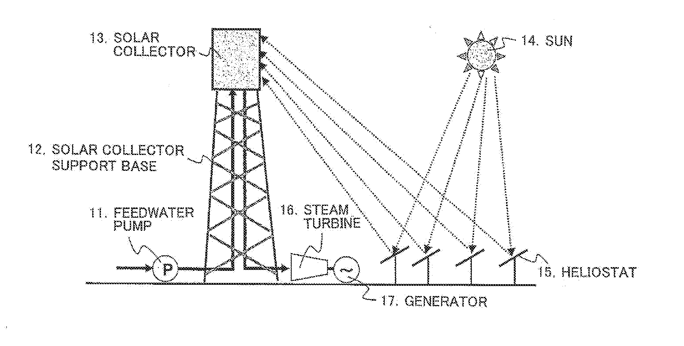
a solar heat boiler and solar collector technology, applied in the safety of solar heat collectors, solar heat generation using solar heat, lighting and heating apparatus, etc., can solve the problem of thermal damage to any member in that portion, and achieve the effect of reducing the total equipment cost of solar heat boilers and avoiding damage to solar collectors

Inactive Publication Date: 2015-07-09
MITSUBISHI HITACHIPOWER SYST LTD
View PDF4 Cites 8 Cited by
  • Summary
  • Abstract
  • Description
  • Claims
  • Application Information

AI Technical Summary

Benefits of technology

The invention reduces the deviation in temperature between the inlet and outlet of a solar heat boiler, which reduces the difference in expansion caused by changes in heating. This prevents damage to the boiler and reduces the cost of equipment. Additionally, the invention reduces the deviation in temperature even when the rate of saturated steam flow or solar radiation fluctuates, making it more efficient and cost-effective.

Problems solved by technology

It is therefore undesirable that the reflected light rays which are incident on a portion other than the heat collection portion of the solar collector may thermally damage any member in that portion.

Method used


Image

  • Solar Collector for Solar Heat Boiler, and Tower-Type Solar Heat Boiler Equipped with Same
  • Solar Collector for Solar Heat Boiler, and Tower-Type Solar Heat Boiler Equipped with Same
  • Solar Collector for Solar Heat Boiler, and Tower-Type Solar Heat Boiler Equipped with Same

Examples


Embodiment Construction

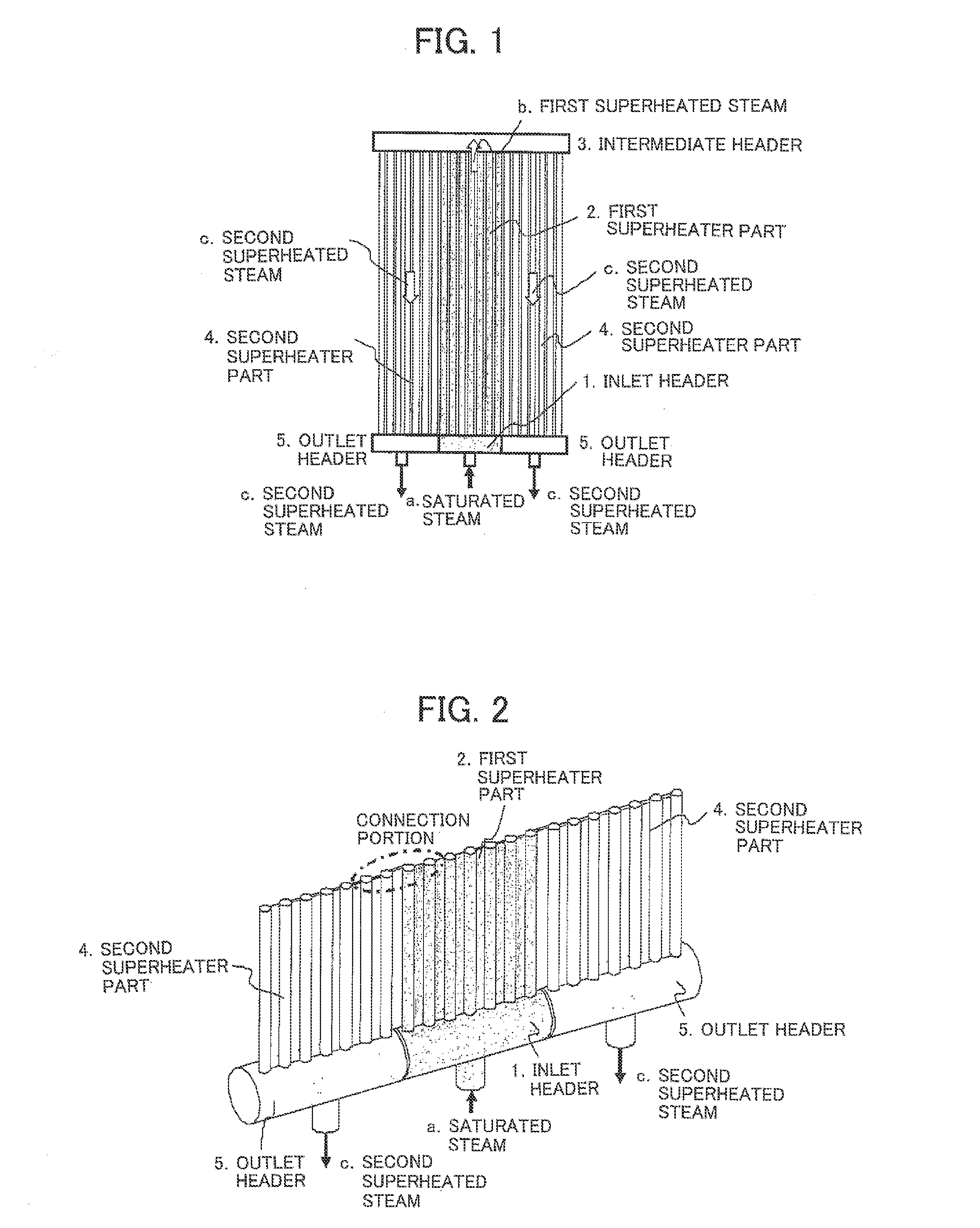
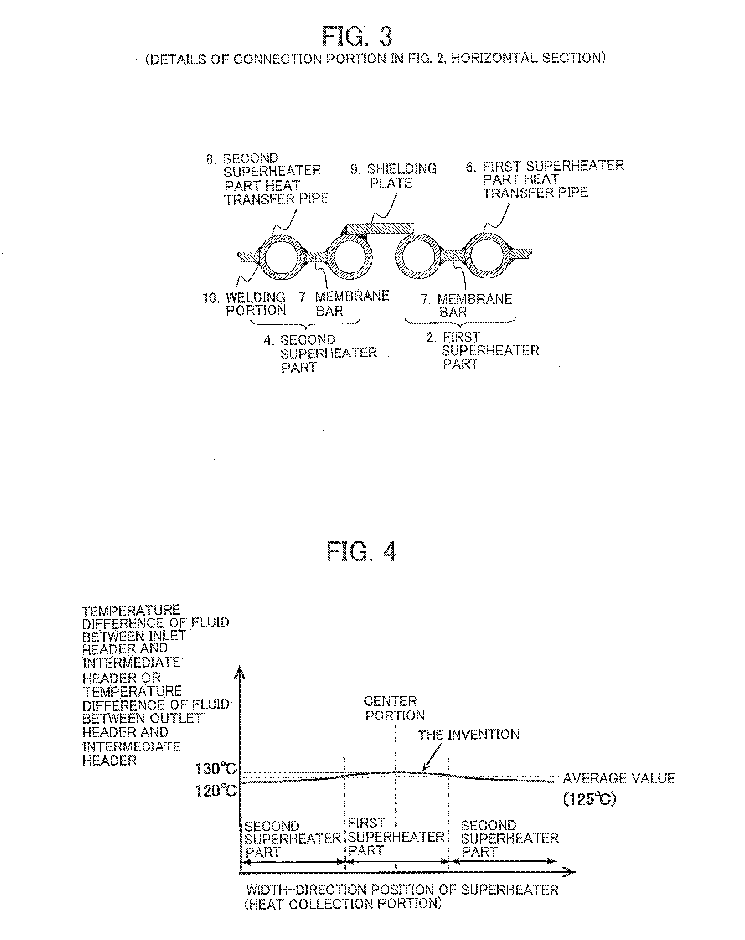
[0037]The configuration and functions of a solar collector for a solar heat boiler according to an embodiment of the invention will be described below in detail with reference to FIG. 1 to FIG. 3. FIG. 1 is a configuration view showing a structure of headers and formation of a fluid flow in the solar collector for a solar heat boiler according to the embodiment of the invention. FIG. 2 is a view showing details of the headers and superheater parts of a superheater in the configuration shown in FIG. 1. FIG. 3 is a sectional view showing details of a connection portion between the superheater parts shown in FIG. 2.

[0038]In FIG. 1, the superheater of the tower-type solar heat boiler according to the embodiment includes an inlet header 1, a first superheater part 2, an intermediate header 3, second superheater parts 4 and outlet headers 5. Saturated steam a flows into the inlet header 1. The first superheater part 2 includes a plurality of heat transfer pipes, in which the saturated ste...


PUM


Abstract

A deviation between an inlet-outlet temperature difference of a first superheater part and an inlet-outlet temperature difference of each of second superheater parts can be reduced so that a difference in thermal expansion between the first superheater part and the second superheater part can be reduced. It is therefore possible to avoid damage on heat transfer pipes. A solar collector for a solar heat boiler is provided with: cylindrical headers (1,3,5) which are connected to opposite end portions of heat transfer pipes; and a solar heat collection portion including the heat transfer pipes and membrane bars fixing the heat transfer pipes to one another; wherein: the cylindrical headers include an inlet header (1) into which a fluid to be heated flows, an intermediate header (3) which is disposed in a position opposed to the inlet header (1) with interposition of the heat transfer pipes, and two outlet headers (5,5) which are provided to extend on opposite end sides of the inlet header and through which the fluid from the intermediate header can be discharged to the outside; and the solar heat collection portion includes a first superheating portion (2) which has a group of the heat transfer pipes connected between the inlet header (1) and the intermediate header (3) so as to form a center region of the solar heat collection portion, and second superheating portions (4,4) which have groups of the heat transfer pipes connected between the intermediate header (3) and the two outlet headers (5) so as to be formed on opposite sides of the first superheating portion (2) respectively.

Description

TECHNICAL FIELD[0001]The present invention relates to a solar collector for a solar heat boiler, which can collect heat from the sun and generate steam by use of the collected heat, and a tower-type solar heat boiler which is equipped with the solar collector.BACKGROUND ART[0002]Concentration type solar heat plants are roughly classified into independent plants and Hybrid plants. In the independent plants, most heat is provided by solar heat while a part of the heat is backed up by fossil fuel or the like. On the other hand, in the Hybrid plants, most heat is provided by fossil fuel or nuclear fuel while a part of the heat is backed up by solar heat.[0003]In both types of the independent plants and the Hybrid plants, heat from sunlight is collected and used as a heating source, and a solar collector is also used substantially in common. Generally, a trough type light / solar collector (in which a parabolic mirror is provided and a heat transfer pipe is disposed at a focal point where ...

Claims


Application Information

Patent Timeline
IPC IPC(8): F24J2/24F24J2/10F24J2/38F22G3/00F22G1/06F24S10/70F24S10/75F24S20/20F24S23/70F24S50/20F24S90/00
CPCF24J2/24F22G3/00F24J2/10F24J2/38F22G1/06F22B1/006F24S10/753F24S20/20F24S40/80F24S80/30Y02E10/44Y02E10/47F24S10/70F24S23/70F24S50/20Y02E10/40
Inventor MARUMOTO, TAKAHIROSHIKATA, TETSUO
Owner MITSUBISHI HITACHIPOWER SYST LTD
Learn More