Optical touch pen

a touch pen and optical technology, applied in the field of optical touch pen, can solve the problems of difficult to trigger the current switch, difficult to assemble the operation module b>12/b> or b>22/b> and the optical pen b>1/b> or b>2/b>, and achieve the effects of reducing the drawback, reducing the sensitivity of the touch control of the optical pen, and simplifying the assembly process

Inactive Publication Date: 2015-07-09
DELTA ELECTRONICS INC
View PDF15 Cites 1 Cited by
  • Summary
  • Abstract
  • Description
  • Claims
  • Application Information

AI Technical Summary

Benefits of technology

[0011]The present invention provides an optical touch pen in order to eliminate the drawbacks that the procedure of assembling a conventional optical pen is complicated, labor-intensive and time-consuming, and the touch control sensitivity of the optical pen is impaired when the multi-directional operations of the conventional optical pen ar

Problems solved by technology

Although the optical pen 1 is electrically conducted in response to the inclined counterforce B, some problems may occur.
Consequently, it is difficult to trigger the current switch 11.
Consequently,

Method used


Image

  • Optical touch pen
  • Optical touch pen
  • Optical touch pen

Examples


Embodiment Construction

[0031]The present invention will now be described more specifically with reference to the following embodiments. It is to be noted that the following descriptions of preferred embodiments of this invention are presented herein for purpose of illustration and description only. It is not intended to be exhaustive or to be limited to the precise form disclosed.

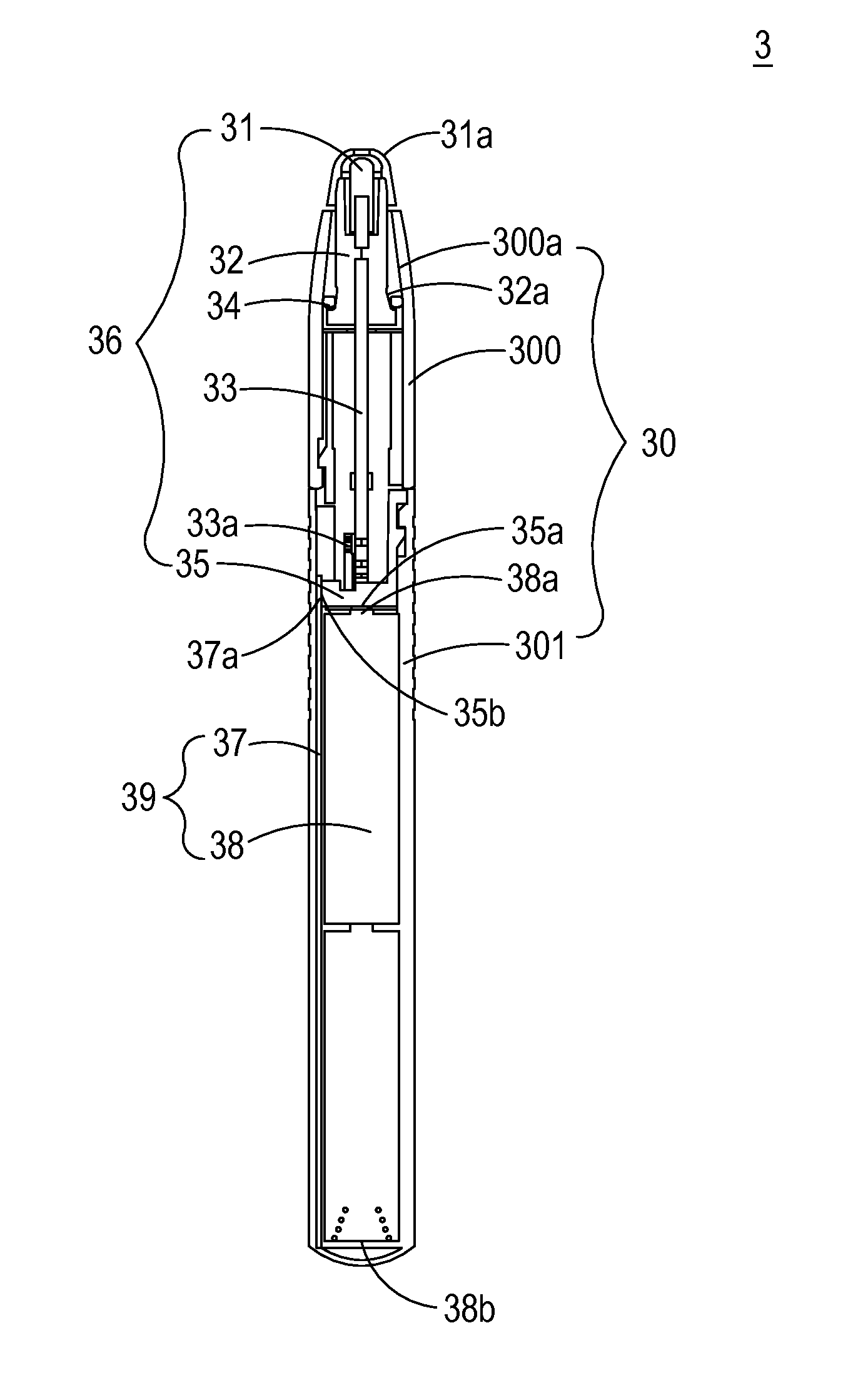
[0032]FIG. 3 is a schematic cross-sectional view illustrating an optical touch pen according to an embodiment of the present invention. As shown in FIG. 3, the optical touch pen 3 comprises a pen case 30, an operation module 36, and a power module 39. The pen case 30 is a pen-like case. The pen case 30 comprises an upper cover 300 and a lower cover 301. The upper cover 300 and the lower cover 301 are hollow structures. The operation module 36 and the power module 39 are disposed within the upper cover 300 and the lower cover 301, respectively. In this embodiment, the operation module 36 comprises a pen tip 31, a supporting part 3...


PUM


Abstract

An optical touch pen includes a pen case, an operation module, and a power module. The operation module is disposed within an upper cover of the pen case, and includes a pen tip, a supporting part, a circuit board and a multi-directional auxiliary element. The multi-directional auxiliary element is arranged between an inner wall of the upper cover and the engaging structure of the supporting part. The power module is disposed within a lower cover of the pen case. When an external force is applied to the pen tip, the pen tip and the supporting part are shifted in response to the external force, the engaging structure of the supporting part is shifted relative to the multi-directional auxiliary element, and the external force is transmitted downwardly to the circuit board. Consequently, a current switch on the circuit board is triggered and the power module is electrically conducted.

Description

CROSS-REFERENCE TO RELATED APPLICATION[0001]This application claims the benefit of U.S. Provisional Application No. 61 / 924,024 filed on Jan. 6, 2014, and entitled “OPTICAL PEN FOR CONTROLLING PROJECTOR”, the entirety of which is hereby incorporated by reference.FIELD OF THE INVENTION[0002]The present invention relates to an optical pen, and more particularly to an optical touch pen capable of performing multi-directional operations.BACKGROUND OF THE INVENTION[0003]With the rapid development of optical projection industries, optical projection systems are widely used as auxiliary tools in conferences or meetings by companies or individuals. Generally, an optical pen can be directly interacted with the optical projection system in real time by tapping a touch screen or performing an editing operation. Consequently, the optical pen is very convenient to the user.[0004]FIG. 1A is a schematic cross-sectional view illustrating a portion of a conventional optical pen. FIG. 1B is a schemati...

Claims


Application Information

Patent Timeline
IPC IPC(8): G06F3/0354G06F3/038
CPCG06F3/03542G06F3/0386G06F3/0383G06F3/03545
Inventor CHEN, HSIN-CHI
Owner DELTA ELECTRONICS INC
Why Eureka
Try Eureka