
Living Room Computer

a living room computer and computer technology, applied in computing, electrical equipment casings/cabinets/drawers, instruments, etc., can solve the problems of not real-time multi-tasking devices, smart tvs, and inability to simultaneously run multiple software applications

Inactive Publication Date: 2015-07-09
ARGO COMP
View PDF21 Cites 19 Cited by
  • Summary
  • Abstract
  • Description
  • Claims
  • Application Information

AI Technical Summary

Benefits of technology

The patent describes a technology that allows users to easily move between different screens on a computer using a swipe of a cursor. For example, users can swipe to switch between different displays of video data, a home screen, an application screen, and a file manager screen. When swiping between these screens, the technology will pause the playback of video data from the current source and display the new screen. Once the user swipes back to the original source, the playback of video data will resume. This technology makes it more efficient and user-friendly for users to switch between different screens and work on their computer.

Problems solved by technology

These internet-capable or internet-ready TV's are commonly referred to as “smart TV's.” A significant drawback of current smart TV's is that they are not true real-time multi-tasking devices.
Further, a smart TV is not capable of simultaneously running multiple software applications with multiple application windows being displayed on the screen at the same time.
Current smart TV's simply lack the processing power, hardware, and software necessary to allow a user to watch a TV program, check the weather, respond to emails, and control Wi-Fi enabled home appliances all at the same time.
But such PCs lack High-Definition Multimedia Interface (HDMI) inputs to enable reception of data from modern electronic devices using HDMI outputs, thus limiting their suitability for entertainment applications.

Method used


Image

  • Living Room Computer
  • Living Room Computer
  • Living Room Computer

Examples


Embodiment Construction

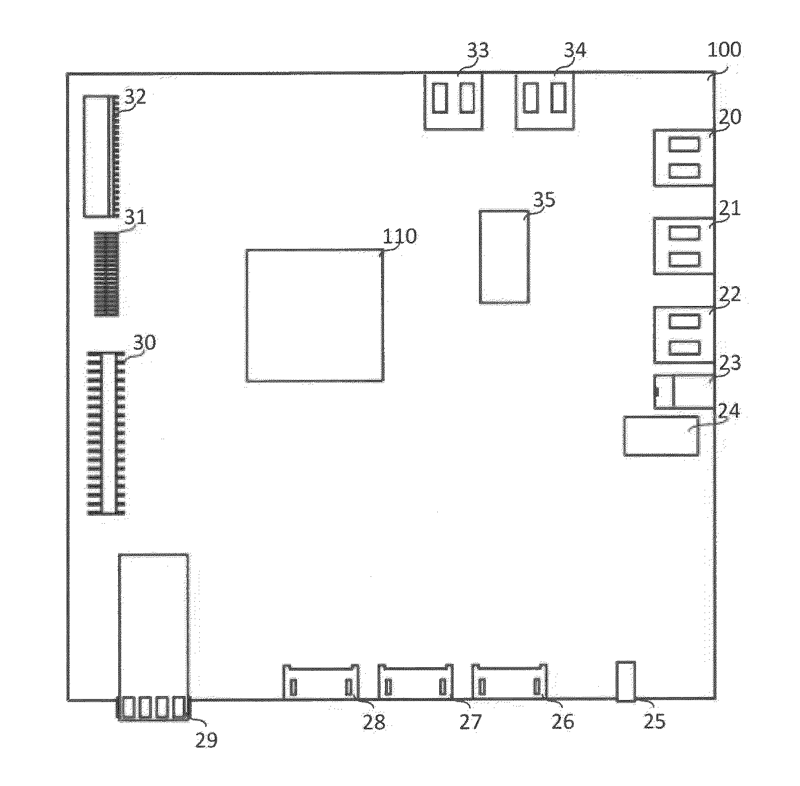
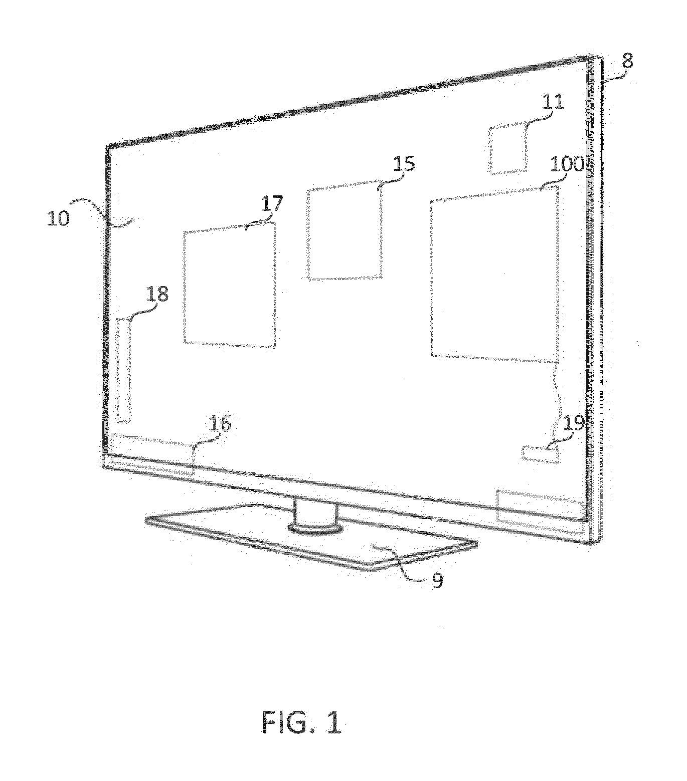
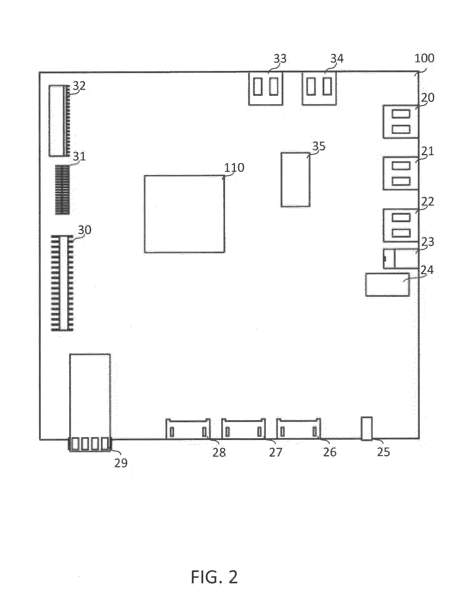
[0034]FIG. 1 shows the main hardware components of one embodiment of the Living Room Computer (LRC). A flat panel display 10 is assembled together with a housing 8 and base 9 for fixing flat panel display 10 in a vertical position. Flat panel display 10 can be, but is not limited to, an LED backlit display, a Direct LED backlit (DLED) display, or an Organic LED backlit (OLED) display. Flat panel display 10 preferably has a diagonal length greater than 30″, and may have a resolution of 1920×1080 pixels, 3840×2160 pixels, or more. Flat panel display 10 is directly connected to a display interface on a main board 100. Audio speakers 16, including but not limited to a left speaker and right speaker for stereo sound, are affixed to the housing 8. A subwoofer 17 may be connected separately to an amplifier on main board 100 or in series with one of audio speakers 16.

[0035]A power supply 15 supplies necessary power to main board 100 and a mass storage device 11 and other components, if nece...


PUM


Abstract

In one embodiment, the living room computer includes a housing, the housing including a small form-factor pluggable (SFP) port, a SFP cage coupled to the SFP port, the SFP cage configured to receive a SFP transceiver, a flat-panel display screen coupled to the housing, and a main board coupled to the flat-panel display screen. The SFP cage is configured to communicate with both optical fiber and copper wire networks. The main board includes a processor, a memory, and an SFP interface coupled to the SFP cage and to the processor. The processor is configured to receive data from the SFP interface and process the data for display on the flat-panel display screen. In one embodiment, the main board includes a wireless module and the processor is configured to process data received from the SFP interface for transmission by the wireless module, and the memory includes software executable by the processor such that the living room computer operates as an IEEE 802.11 access point.

Description

CROSS-REFERENCE TO RELATED APPLICATION[0001]This application claims the benefit of U.S. Provisional Patent Application No. 61 / 924,117, entitled “Living Room Computer,” filed on Jan. 6, 2014. The subject matter of the related application is hereby incorporated by reference in its entirety.FIELD OF THE INVENTION[0002]This invention relates generally to computing devices and more specifically to a living room computer.BACKGROUND[0003]Until fairly recently, consumer televisions (TV's) have been only capable of doing one thing: displaying audio-visual data from either a cable, satellite, or other transmission source. In the late-2000's, TV's capable of browsing the Internet started becoming available in the consumer marketplace. These internet-capable or internet-ready TV's are commonly referred to as “smart TV's.” A significant drawback of current smart TV's is that they are not true real-time multi-tasking devices. With a smart TV, the user can only browse the internet and watch a TV p...

Claims


Application Information

Patent Timeline
IPC IPC(8): H04N21/4143H04N21/4363G06F1/16
CPCH04N21/4143H04N21/43637H04N21/43632G06F1/1601H04N21/41
Inventor SYNOWIEC, CHRISTIAN
Owner ARGO COMP
Learn More