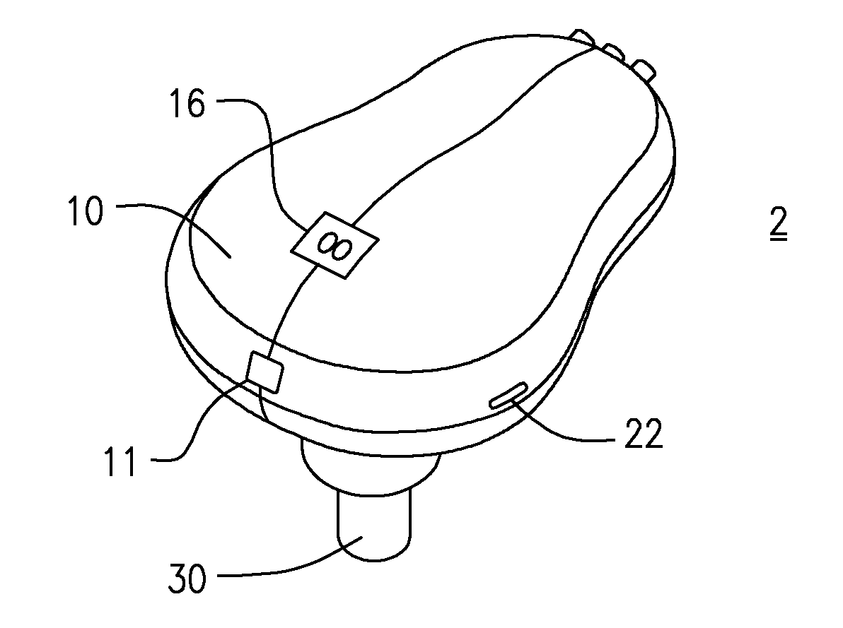
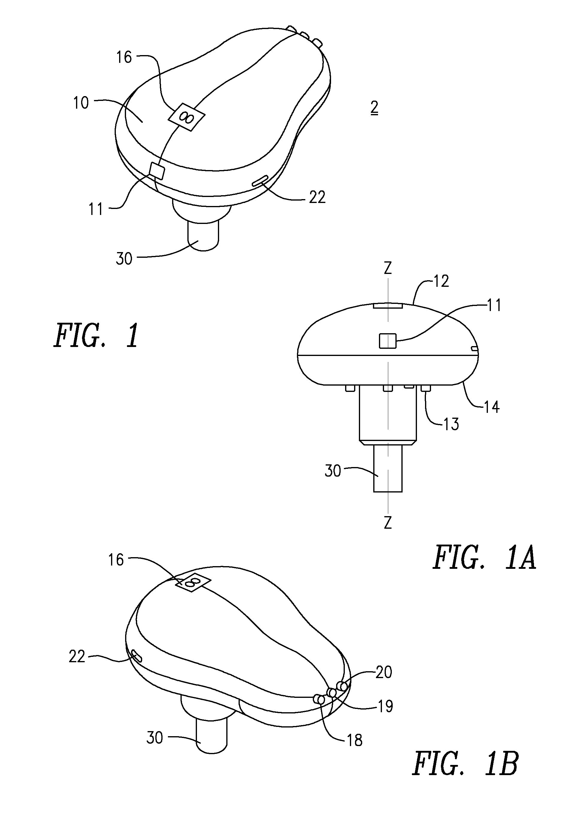
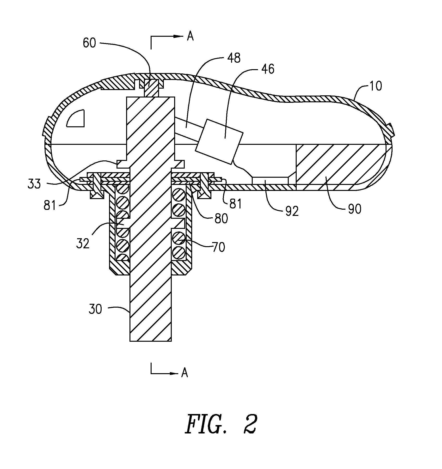
Impactor and remover devices

a technology of impactors and removers, applied in the field of impactors, can solve the problems of affecting the efficiency of surgeons, and affecting the efficiency of surgeons, and achieves the effects of less risk of injury, less peak force, and same or greater total energy of delivery

Inactive Publication Date: 2015-07-16
ARCHER SCI
View PDF18 Cites 59 Cited by
  • Summary
  • Abstract
  • Description
  • Claims
  • Application Information

AI Technical Summary

Benefits of technology

[0011]In some embodiments impactors are disclosed which are operable to apply low amplitude, high frequency impact. Utilizing a high-frequency impact

Problems solved by technology

These high peak impact forces predispose the bone or soft tissue to mechanical failure or injury.
Furthermore, high sudden peak forces make it more difficult to center the tool or implant.
However, challenges exist when impacting or inserting devices, include surgeon fatigue, harm to the patient, harm to the device, whether it be the instrument or implant, and the need for multiple types of impactors or inserters depending

Method used


Image

  • Impactor and remover devices
  • Impactor and remover devices
  • Impactor and remover devices

Examples


Embodiment Construction

[0057]The present invention now will be described more fully hereinafter with reference to the accompanying drawings, in which illustrative embodiments of the invention are shown. In the drawings, the relative sizes of regions or features may be exaggerated for clarity. This invention may, however, be embodied in many different forms and should not be construed as limited to the embodiments set forth herein; rather, these embodiments are provided so that this disclosure will be thorough and complete, and will fully convey the scope of the invention to those skilled in the art.

[0058]It will be understood that when an element is referred to as being “coupled” or “connected” to another element, it can be directly coupled or connected to the other element or intervening elements may also be present. In contrast, when an element is referred to as being “directly coupled” or “directly connected” to another element, there are no intervening elements present Like numbers refer to like eleme...


PUM


Abstract

An impactor having a housing including an upper portion and a lower portion at least a part of which extends perpendicularly from the upper portion, a ram having a first end positioned in the upper portion and positioned in axial alignment with the lower portion, an opposite end of the ram extending from the lower portion of the housing, at least one drive assembly including a first drive shaft operably coupled to a cam shaft, a cam operably coupled to the cam shaft, a cam operably coupled to the cam shaft, the drive shaft operably connectable to motor, wherein the cam is operable to rotate and positioned to contact the proximal end of the ram upon rotation of the cam, a circuit board comprising circuitry operable to receive instructions from a plurality of switches electrically coupled to the circuit board to operate the impactor, wherein the impactor is operable to deliver low amplitude pulsed strikes to a workpiece at variable frequencies.

Description

CROSS-REFERENCE TO RELATED APPLICATIONS[0001]This application claims the benefit of U.S. Provisional Application No. 61 / 928,011 filed Jan. 16, 2014, the entirety of which is incorporated herein by reference.FIELD OF THE INVENTION[0002]This invention relates to the field of impactors. More specifically it relates to medical device impactor instruments.BACKGROUND[0003]Surgery, more specifically orthopedic surgery, often requires the surgeon to apply significant forces to the anatomy in order to achieve a desired result. Insertion of medical devices, particularly orthopedic, typically involves repetitive low-frequency and high magnitude forces, commonly from a mallet or hammer. These high peak impact forces predispose the bone or soft tissue to mechanical failure or injury. Furthermore, high sudden peak forces make it more difficult to center the tool or implant.[0004]For example, a surgeon may need to remove bony anatomy by chiseling. Chiseling typically requires at least two tools: a...

Claims


Application Information

Patent Timeline
IPC IPC(8): A61B17/92
CPCA61B17/92A61B2017/924A61B2017/00734A61B2017/00398A61B17/1604A61B17/1626A61B90/30A61B2017/00119A61B2017/00141A61B2017/00199A61B2090/064
Inventor DONALD, GORDONALFARO, ARTHURKIEFER, LAWRENCESTRAUSS, KEVIN
Owner ARCHER SCI
Why Eureka
Try Eureka