Imaging system and method for enabling instrument guidance

a technology of instrument guidance and imaging system, applied in the field of imaging system, can solve the problems of increased radiation exposure and complicated mechanical properties, and achieve the effect of easy and/or accurately established and accurate establishmen

Active Publication Date: 2015-07-23
KONINKLJIJKE PHILIPS NV
View PDF8 Cites 52 Cited by
  • Summary
  • Abstract
  • Description
  • Claims
  • Application Information

AI Technical Summary

Benefits of technology

[0006]It would be advantageous to have a system or method for enabling instrument guidance which is less mechanically complex and / or minimizes radiation exposure.
[0044]Optionally, the processor is arranged for establishing the spatial correspondence based on spatial correspondence data obtained during a calibration phase of the imaging system, the calibration phase comprising establishing a relative position between the camera and the imaging system. Since the camera is part of the imaging system, the relative position between the camera and the imaging system is known or can be determined to a certain degree. By establishing their relative position during a calibration phase, said relative position can be taken into account so as to allow the spatial correspondence between the camera image and the 3D image data to be more easily and / or accurately established. Advantageously, in case the camera is rigidly affixed to the imaging system, the relative position between the camera and the imaging system is fixed throughout various interventional procedures, and therefore, a single calibration phase suffices, i.e., it is not needed to update the spatial correspondence continuously during and / or between interventions for changes in the relative position between the camera and the imaging system. Rather, it is only needed to update the spatial correspondence for changes in the relative position between the camera and the patient, which may be obtained from, e.g., position information of a C-arm in case the camera is affixed to a C-arm of an X-ray imaging system.

Problems solved by technology

A problem of the above system is that it mechanically complex.
A further problem of the above system is that it can result in increased radiation exposure.

Method used


Image

  • Imaging system and method for enabling instrument guidance
  • Imaging system and method for enabling instrument guidance
  • Imaging system and method for enabling instrument guidance

Examples


Embodiment Construction

[0060]In the following, the imaging system is, by way of example, chosen to be an X-ray imaging system. It will be appreciated, however, that the present invention is equally applicable to other types of imaging systems, e.g., MRI, CT, PET, etc.

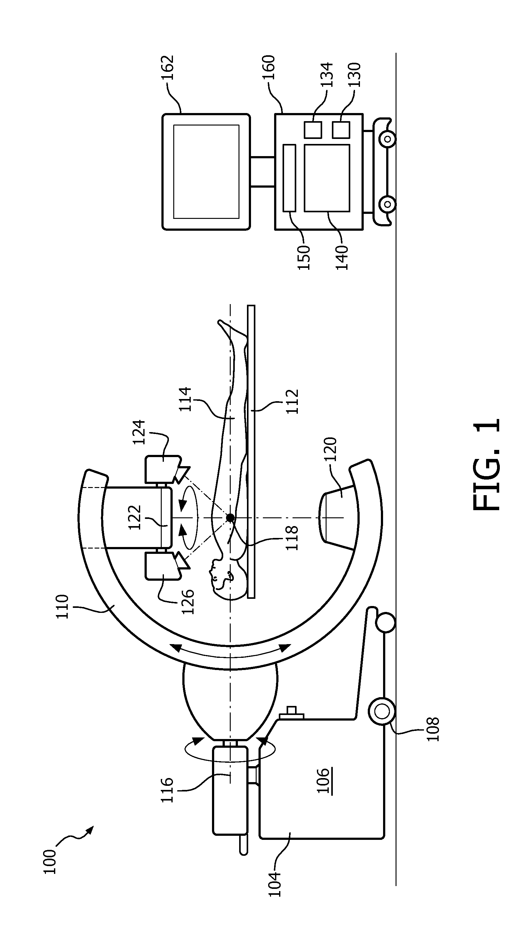
[0061]FIG. 1 shows an X-ray imaging system 100 comprising an X-ray device 104 for providing an X-ray image of a patient's interior. The X-ray device 104 comprises a base frame 106 supported by wheels 108, a C-arm 110 and a surgical table 112 for supporting a patient 114. In this particular example, the patient 114 is shown to be a human patient. The C-arm 110 is rotatable with respect to a first axis 116 being oriented along a main orientation of the surgical table 112. The C-arm 110 is further rotatable with respect to a second axis 118 which is perpendicular to the first axis 116 and parallel to the surgical table 112. An X-ray source 120 and an X-ray detector 122, shown to be a rectangular and flat detector, are mounted on the C-arm 110 su...


PUM


Abstract

Imaging system (100) for enabling instrument guidance in an interventional procedure, comprising: —an input (130) for obtaining an interventional path (220) for use in the interventional procedure, the interventional path being planned based on 3D image data (200) of a patient's interior, and the interventional path being indicative of an entry point (230) on the patient's exterior; —a camera (124-127) for obtaining a camera image (270) of the patient's exterior during the interventional procedure; —a processor (140) for i) establishing a spatial correspondence between the camera image and the 3D image data, ii) based on the spatial correspondence, calculating a view (280) of the interventional path that corresponds with the camera image, and iii) combining the view of the interventional path with the camera image to obtain a composite image (290); and —a display output (150) for displaying the composite image on a display (162).

Description

FIELD OF THE INVENTION[0001]The invention relates to an imaging system for enabling instrument guidance in an interventional procedure. The invention further relates to a method for enabling instrument guidance in an interventional procedure, and to a computer program product comprising instructions for causing a processor system to perform the method.[0002]In interventional procedures, such as surgeries, biopsies, etc, clinicians frequently make use of imaging systems to obtain a view of the patient's interior. For that purpose, imaging modalities such as standard X-ray imaging, Computed Tomography (CT), Magnetic Resonance Imaging (MRI), etc, may be used. The view of the patient's interior may enable the clinician to obtain instrument guidance, i.e., guidance on a position and orientation of an interventional instrument with respect to a target area in the patient's interior, on account of the interventional instrument being visible in the view of the patient's interior. As a resul...

Claims


Application Information

Patent Timeline
Patent Type & Authority Applications(United States)
IPC IPC(8): A61B6/12G06T19/00A61B6/00G06F19/00
CPCA61B6/12G06F19/321G06F19/3437G06T2210/41G06T19/006A61B6/5247G06F19/3481A61B6/466G06T19/00A61B6/102A61B6/42A61B6/4441A61B6/5229A61B6/582A61B90/37A61B2034/107A61B2090/3612A61B2090/365A61B2090/371A61B2090/376A61B2090/3764G16H20/40G16H30/20G16H50/50
Inventor HUMMEL, ERIKHOMAN, ROBERT JOHANNES FREDERIKBABIC, DRAZENKOBALGUID, ANGELIQUE
Owner KONINKLJIJKE PHILIPS NV
Why Eureka
Try Eureka