Landing gear joint lubrication

a technology for landing gear joints and lubricating agents, which is applied in the direction of mechanical equipment, transportation and packaging, bearing repair/replacement, etc., can solve the problems of increasing the period between maintenance intervals and the recirculation of lubricating agents, and achieve the effect of reducing the risk of prolonged interruption

Pending Publication Date: 2021-08-26
AIRBUS OPERATIONS LTD
View PDF5 Cites 3 Cited by
  • Summary
  • Abstract
  • Description
  • Claims
  • Application Information

AI Technical Summary

Benefits of technology

[0008]When the pin assembly is inserted into a pin joint, the provision of bi-directional flow paths into both the first and second chambers allows for lubricating agent to flow back and forth between the first and second chambers along the same flow path as the piston moves back and forth in the reservoir. This recirculation of lubricating agent may increase the period between maintenance intervals when compared to devices which simply eject lubricating agent from the reservoir. Additionally or alternatively, the reversing flow direction may improve the distribution of grease across the joint and / or reduce the likelihood of the blockages, for example from lubricating agent hardening within the joint. The provision of such bi-directional flow paths may also lead to a device that is less mechanically complex than other prior art lubrication devices that provide recirculation of lubricant, thereby increasing reliability of the device and / or reducing weight and / or cost of the device.
[0051]The first and second pin inserts may be pin inserts and / or form part of a pin assembly as described above for any other aspect. The method may provide for improved reliability of maintenance by removing the need for maintenance operatives to identify all grease nipples when supplying grease to a joint. Additionally or alternatively, the method may reduce the time required to replenish the lubricating agent in a pin joint as a maintenance operative simply swaps one cartridge for another, rather than spending time using a grease gun to inject grease into the joint.

Problems solved by technology

This recirculation of lubricating agent may increase the period between maintenance intervals when compared to devices which simply eject lubricating agent from the reservoir.

Method used


Image

  • Landing gear joint lubrication
  • Landing gear joint lubrication
  • Landing gear joint lubrication

Examples


Embodiment Construction

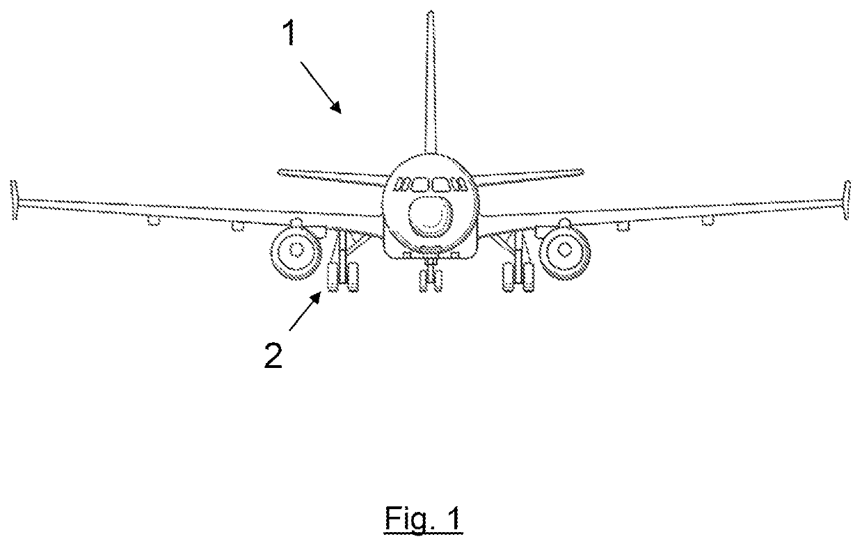
[0064]FIG. 1 shows an aircraft 1 including main landing gear 2 according to embodiments of the invention. In the same or further embodiments the invention may find application in nose landing gear.

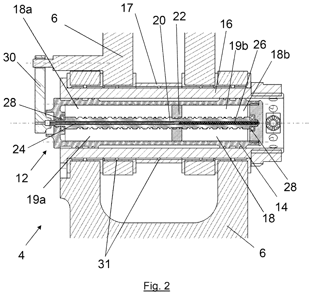
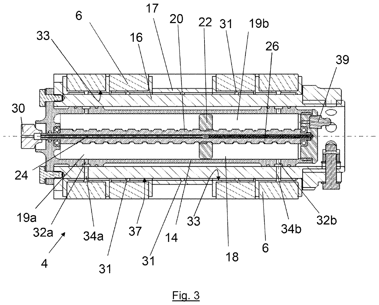
[0065]FIG. 2 shows a cross-sectional view through a pin joint 4 between two components 6 of main landing gear 2. Examples of such pin joints 4 may be found in the torque link assembly, drag stay assemblies, side stay assemblies, link assemblies and / or main fitting of a landing gear. In some embodiments pin joints as described herein may be found in the nose landing gear. The structure of each component 6 defines a cylindrical bore in which a lubrication device 12 in accordance with an embodiment of the invention is received. The lubrication device 12 comprises a main body 14 which is concentrically received within a hollow pin 16 itself concentrically received in a bushing 17 which is concentrically received in the cylindrical bore. It will be appreciated that in some embodiments bushing 1...


PUM


Abstract

A pin assembly for insertion into a pin joint of an aircraft landing gear is disclosed. The pin assembly includes a reservoir for storing a lubricating agent and a piston mounted for reciprocal movement within the reservoir, the piston dividing the reservoir into a first chamber and a second chamber. A bi-directional flow path between the first and second chambers via the surface to be lubricated is provided by means of a first bi-directional flow path between the first chamber and the exterior of the pin assembly and a second bi-directional flow path between the second chamber and the exterior of the pin assembly. A pin assembly including an indicator system, and a pin insert in the form of a replaceable cartridge is also disclosed along with associated methods.

Description

BACKGROUND OF THE INVENTION[0001]The present invention concerns lubrication, for example greasing, of pin joints on aircraft landing gear. More particularly, but not exclusively, this invention concerns methods and apparatus for self-lubricating pin joints. The invention concerns a pin assembly for use in a pin joint of an aircraft landing gear, an aircraft landing gear having a pin joint comprising such a pin assembly, a method of lubricating a pin joint of an aircraft landing gear using such a pin assembly, and a method of lubricating a pin joint of an aircraft landing gear using a pin insert comprising elements of such a pin assembly.[0002]Aircraft landing gear often include one or more dynamic pin joints (hereafter pin joints) to provide pivotal movement of one component relative to the other, for example during extension and retraction of the landing gear. Typically, such joints comprise a pin and structure on one or more of the components that defines a hole in which the pin i...

Claims


Application Information

Patent Timeline
Patent Type & Authority Applications(United States)
IPC IPC(8): B64C25/00B64D45/00
CPCB64C25/001B64D45/0005B64C25/02B64C25/18F16C2326/43F16C11/045F16C33/102F16C2237/00F16N7/20F16N2210/08B64C25/00F16N7/36
Inventor HOLT, RICHARD
Owner AIRBUS OPERATIONS LTD
Why Eureka
Try Eureka