Supercharge Your Innovation With Domain-Expert AI Agents!

Grinding wheel and method

a technology of grinding wheel and grinding plate, which is applied in the direction of grinding/polishing safety devices, maintenance and safety accessories, abrasives, etc., can solve the problems of equipment damage, wheel failure and part damag

Active Publication Date: 2015-07-23
PRATT & WHITNEY CANADA CORP
View PDF22 Cites 3 Cited by
  • Summary
  • Abstract
  • Description
  • Claims
  • Application Information

AI Technical Summary

Benefits of technology

The patent is for a grinding wheel with a unique structure that helps to distribute coolant to the grinding site in an efficient way. The wheel has blades that create grooves that allow the coolant to flow through the wheel and be expelled at an angle of up to 15 degrees. This results in a more effective cooling process and better performance of the grinding wheel. The technical effects of this patent include improved cooling efficiency, better performance, and reduced wear and tear of the grinding wheel.

Problems solved by technology

Failure to deliver the required amount of coolant at the correct location may result in wheel failure and part damage, and may also cause equipment damage in case of fire when using oil based coolants.

Method used


Image

  • Grinding wheel and method
  • Grinding wheel and method
  • Grinding wheel and method

Examples


Embodiment Construction

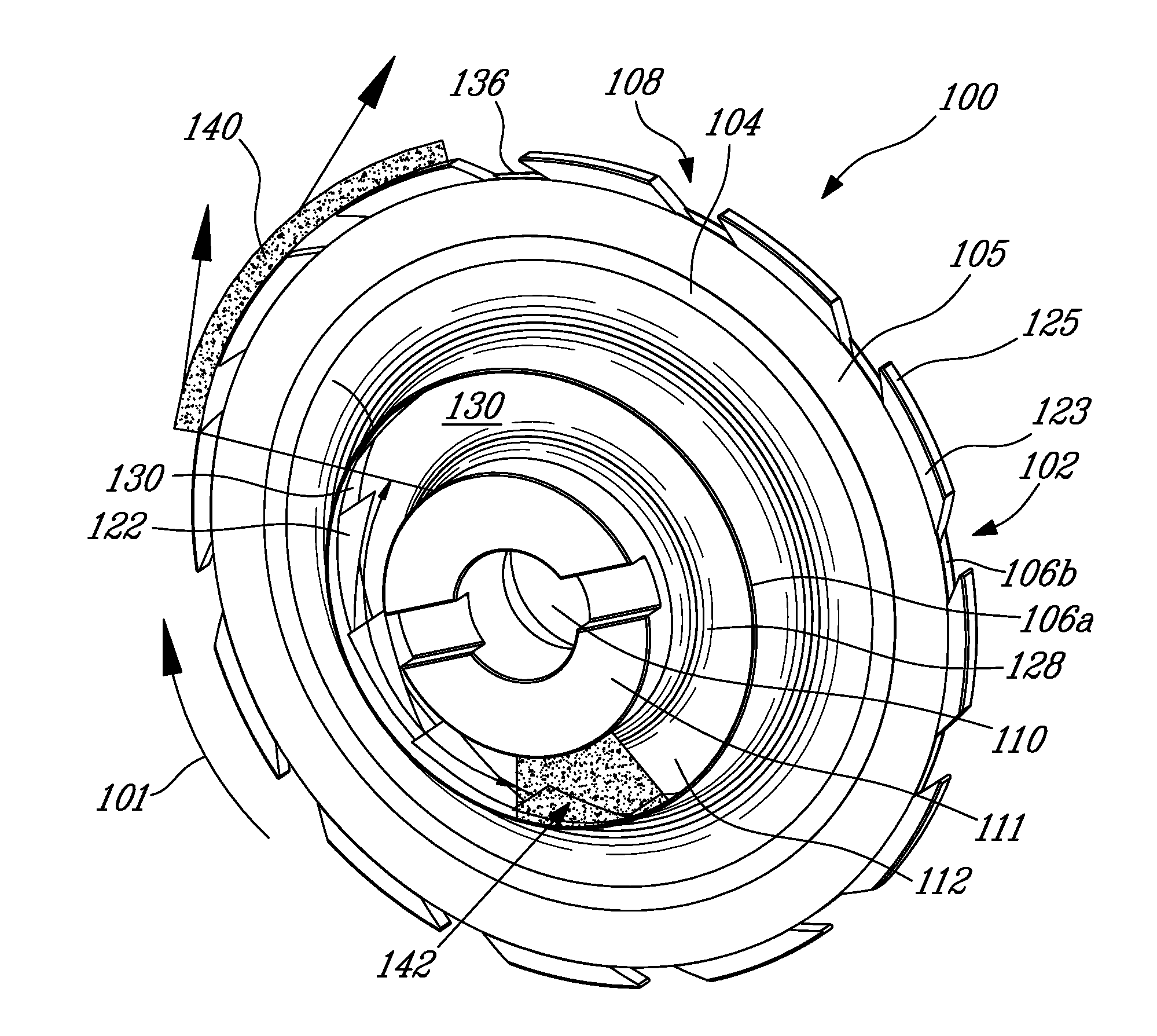
[0015]A grinding wheel will be described herein. Such a grinding assembly may be used, for example, in machining of components of a gas turbine engine, including, but not limited to, turbine discs, integrally bladed rotors.

[0016]Conventional methods of coolant delivery usually rely on using external nozzles to bring coolant into the machining zone in a spraying technique. Such a technique may be limited to having a clear line of sight from nozzle orifice to the machining zone. In case of grinding of internal part features, the line of sight is often blocked and it may require a complicated nozzle design to reach the machining zone; the nozzle may also provide interference in the tool path to avoid collision with the part. Accordingly, a grinding wheel providing internal coolant delivery is described herein.

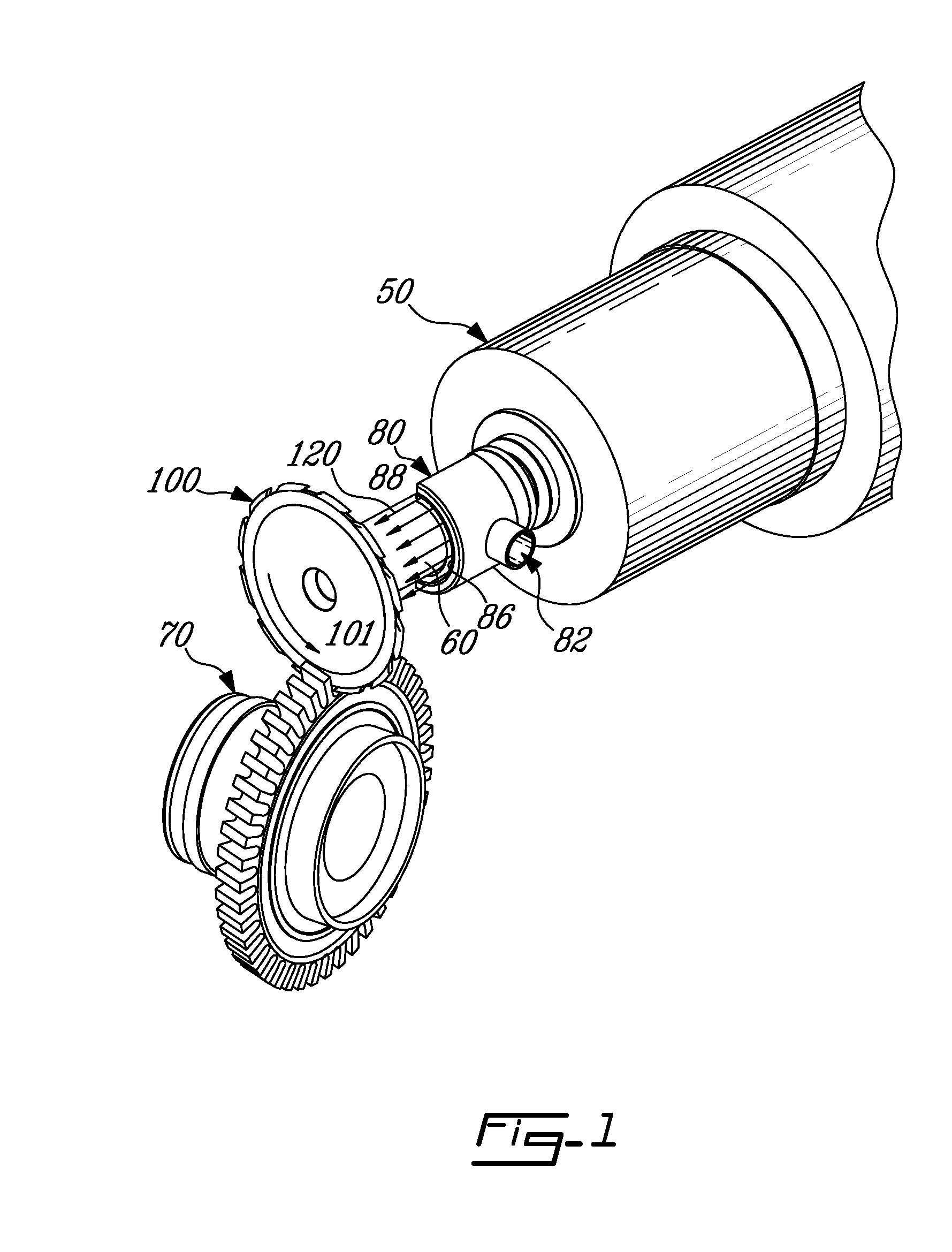
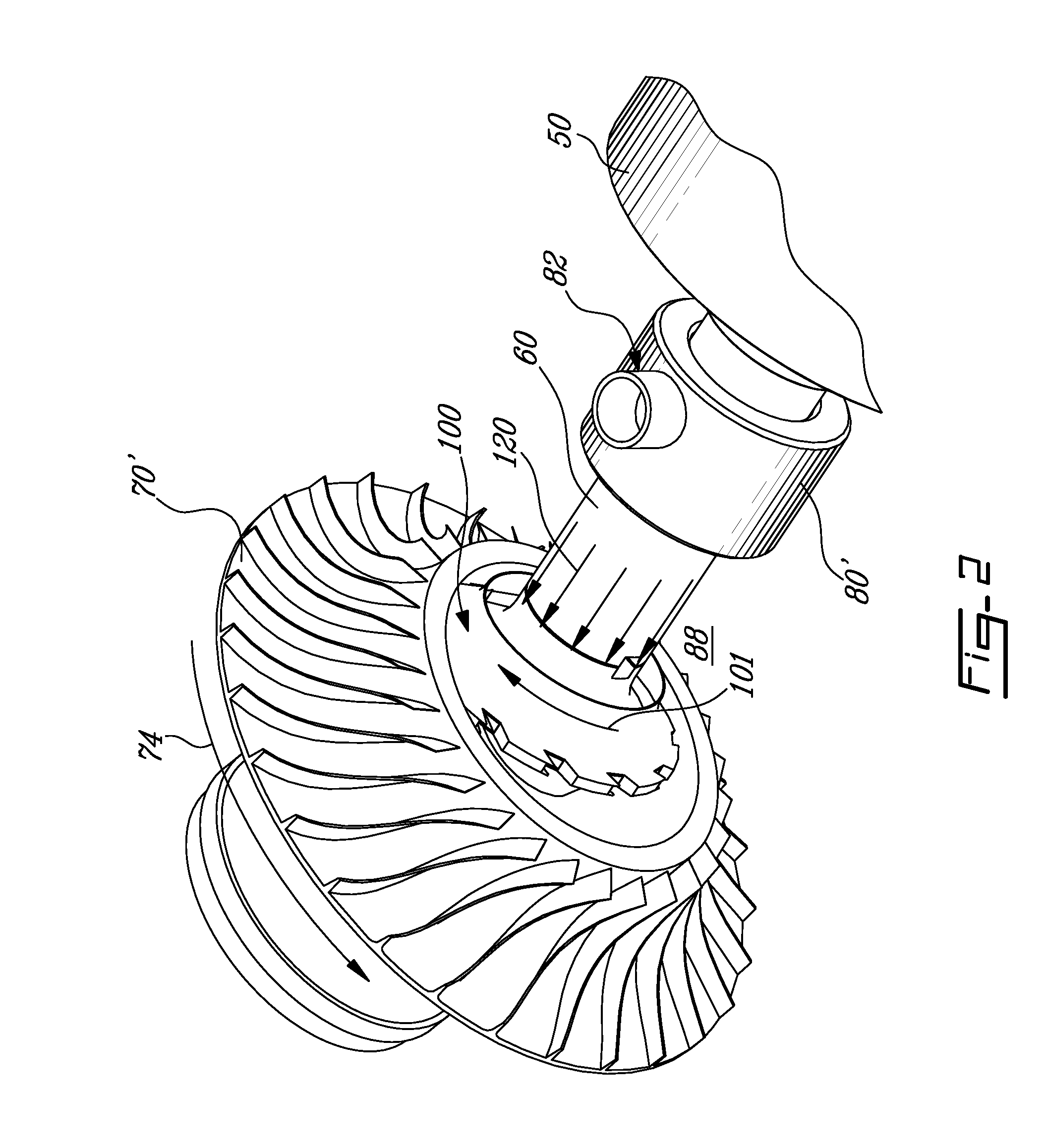
[0017]Referring to FIGS. 1 to 4, the grinding wheel 100 is shown connected to a machine spindle 50 by a rotatable shaft 60. The shaft 60 entrains the grinding wheel 100 in rotatio...


PUM

PropertyMeasurementUnit
angleaaaaaaaaaa
angle a2aaaaaaaaaa
angle a2aaaaaaaaaa

Abstract

A grinding wheel including an impeller structure for circulating coolant within the wheel defining a plurality of grooves. An angle between a second wall of each groove and a tangent to the outer circumference adjacent the groove outlet is defined based on the desired coolant flow rate, the predetermined wheel rotational speed, the radius of the outer circumference of the impeller structure, the combined surface area of the groove outlets, and a desired angle of exit of the coolant being at most 15 degrees. Also, a wheel is disclosed where the angle of the second wall of each groove is defined based on the desired coolant flow rate, the combined surface area of the groove outlets, the tangential speed of the wheel, and a value of n being at least 0.9 and less than 1. A method for distributing a coolant to a grinding site is also discussed.

Description

TECHNICAL FIELD[0001]The application relates generally to grinding wheels and, more particularly, to cooling in such grinding wheels.BACKGROUND OF THE ART[0002]When a grinding wheel grinds or machines a workpiece, heat is generated at the grinding zone. Coolant delivery to the machining zone ensures the extraction of heat, but also provides lubricity and allows for chip evacuation. Failure to deliver the required amount of coolant at the correct location may result in wheel failure and part damage, and may also cause equipment damage in case of fire when using oil based coolants. Superabrasive machining processes are particularly sensitive to coolant delivery, and coolant should be delivered as close as possible to the machining zone.SUMMARY[0003]In one aspect, there is provided a grinding wheel for grinding a workpiece through rotation at a predetermined rotational speed, the wheel comprising: a grinding wheel body having a hub defining a wheel inlet; and an impeller structure disp...

Claims


Application Information

Patent Timeline
Patent Type & Authority Applications(United States)
IPC IPC(8): B24D5/10
CPCB24D5/10B24B55/02B24D7/10B23Q11/12
Inventor ELFIZY, AMRPERRON, FRANCOIS
Owner PRATT & WHITNEY CANADA CORP
Features
  • R&D
  • Intellectual Property
  • Life Sciences
  • Materials
  • Tech Scout
  • Unparalleled Data Quality
  • Higher Quality Content
  • 60% Fewer Hallucinations
Learn More